ESP8266 NodeMCU Controlled Environmental Monitoring System with LCD Feedback
Circuit Documentation
Summary
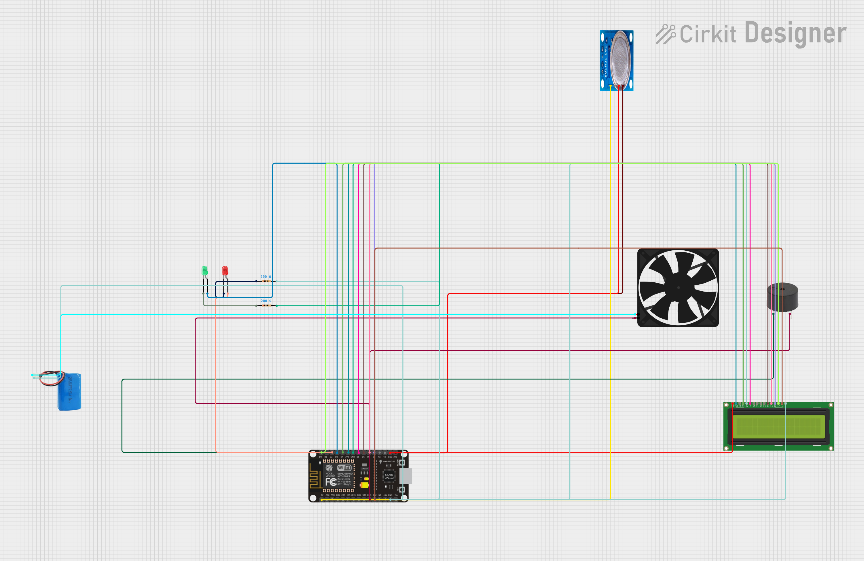
The circuit described in the provided design includes a variety of components that are interconnected to perform specific functions. The main controller of the circuit is an ESP8266 NodeMCU microcontroller, which interfaces with several peripherals including LEDs, a buzzer, a fan, an MQ-5 gas sensor, and an LCD display. The circuit is powered by a 5V battery. The LEDs are current-limited by resistors, and the microcontroller controls the LEDs, buzzer, and LCD display. The MQ-5 sensor provides analog gas concentration readings to the microcontroller. The fan is directly powered by the battery.
Component List
LEDs
- Red LED: A two-pin red LED that emits red light when powered.
- Green LED: A two-pin green LED that emits green light when powered.
Resistors
- 200 Ohm Resistors: Two resistors with a resistance of 200 Ohms each, used to limit the current through the LEDs.
Buzzer
- Buzzer: An electromechanical component that emits sound when powered.
Fan
- Fan: A small DC fan that operates at 5V.
ESP8266 NodeMCU
- ESP8266 NodeMCU: A microcontroller with WiFi capabilities and multiple digital and analog pins for interfacing with various components.
MQ-5 Gas Sensor
- MQ-5 Gas Sensor: A sensor used for detecting various gases, including natural gas and LPG.
LCD Display 16x2
- LCD Display 16x2: A liquid crystal display capable of showing 16 characters per line on 2 lines.
5V Battery
- 5V Battery: A power source for the circuit.
Wiring Details
Red LED
- Cathode: Connected to one terminal of a 200 Ohm resistor.
- Anode: Controlled by the D2 pin of the ESP8266 NodeMCU.
Green LED
- Cathode: Connected to one terminal of a 200 Ohm resistor.
- Anode: Controlled by the D3 pin of the ESP8266 NodeMCU.
200 Ohm Resistors
- Resistor 1: One terminal connected to the cathode of the red LED, the other terminal connected to the common ground net.
- Resistor 2: One terminal connected to the cathode of the green LED, the other terminal connected to the common ground net.
Buzzer
- PIN: Controlled by the D1 pin of the ESP8266 NodeMCU.
- GND: Connected to the common ground net.
Fan
- 5V: Connected to the positive terminal of the 5V battery.
- GND: Connected to the common ground net.
ESP8266 NodeMCU
- GND: Connected to the common ground net.
- 3V3: Powers the VCC of the MQ-5 gas sensor and the VDD and LEDA pins of the LCD Display 16x2.
- D0-D8: Control various pins of the LCD Display 16x2.
- A0: Reads the analog output from the MQ-5 gas sensor.
MQ-5 Gas Sensor
- VCC: Powered by the 3V3 pin of the ESP8266 NodeMCU.
- GND: Connected to the common ground net.
- Analog out: Connected to the A0 pin of the ESP8266 NodeMCU.
LCD Display 16x2
- VSS, RW, LEDK: Connected to the common ground net.
- VDD: Powered by the 3V3 pin of the ESP8266 NodeMCU.
- LEDA: Powered by the 3V3 pin of the ESP8266 NodeMCU.
- DB0-DB7: DB4-DB7 are controlled by the D6-D8 and D0 pins of the ESP8266 NodeMCU, respectively.
- RS: Controlled by the D4 pin of the ESP8266 NodeMCU.
- E: Controlled by the D5 pin of the ESP8266 NodeMCU.
5V Battery
- Positive: Powers the Fan and is part of the common ground net.
- Negative: Connected to the common ground net.
Documented Code
No code has been provided for the microcontroller. The documentation of the code would typically include descriptions of the functions, initialization routines, main loop, and any interrupt service routines. It would also detail how the microcontroller interfaces with each component, including the setup of I/O pins, the logic for controlling outputs, and the handling of inputs from sensors.