Wi-Fi Controlled Smart Lighting and Door Automation with ESP8266 and Motion Sensor
Circuit Documentation
Summary
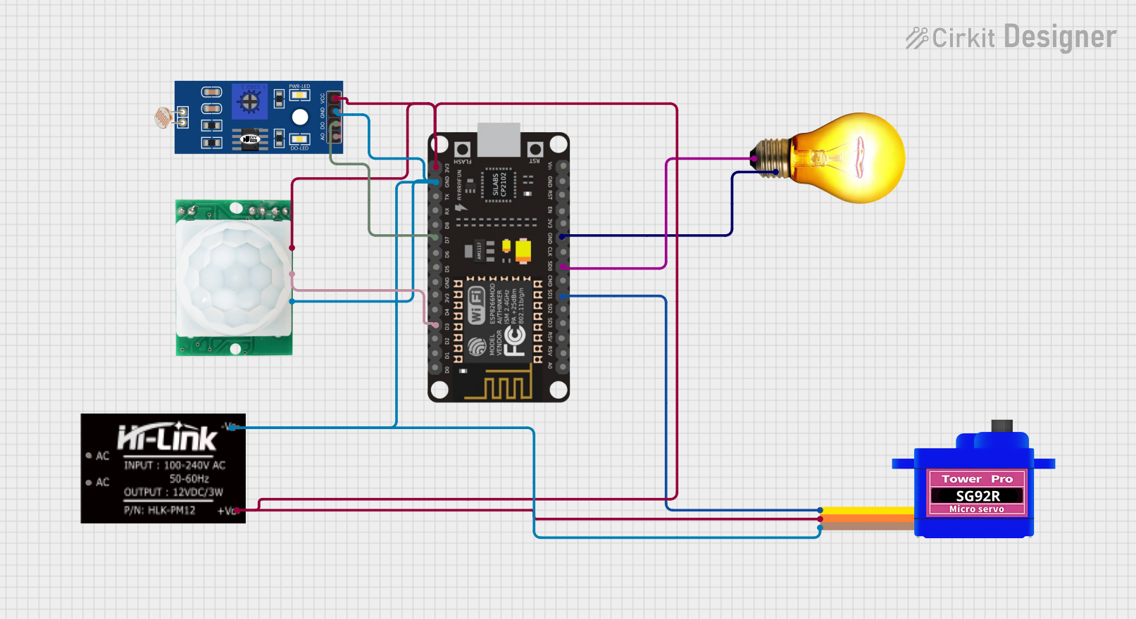
The circuit is designed to control an AC bulb and a servomotor (SG92R) through an ESP8266 NodeMCU microcontroller. The NodeMCU is connected to a motion sensor (HC-SR501) and a light-dependent resistor (LDR) to detect motion and light levels, respectively. The microcontroller can be manually controlled via a web server hosted on the NodeMCU, allowing the user to open/close the servomotor (acting as a door) and turn the AC bulb on/off. The circuit is powered by an HLK-PM12 AC-DC converter, providing a stable 3.3V supply to the components.
Component List
- HLK-PM12: An AC-DC converter that provides a 3.3V DC output from an AC input.
- HC-SR501 Motion Sensor: A PIR motion sensor used to detect movement within its range.
- AC Bulb: A standard AC-powered light bulb.
- LDR (Light-Dependent Resistor): A sensor that changes resistance based on the ambient light level.
- Servomotor SG92R: A small servo motor capable of precise position control.
- ESP8266 NodeMCU: A microcontroller with built-in Wi-Fi capabilities, used for controlling the circuit and hosting a web server.
Wiring Details
HLK-PM12
+V0: Connected to the 3.3V power rail supplying the NodeMCU, motion sensor, LDR, and servomotor.-V0: Connected to the ground rail shared by all components.
HC-SR501 Motion Sensor
GND: Connected to the ground rail.OUT: Connected to theD3pin on the ESP8266 NodeMCU.VCC: Connected to the 3.3V power rail.
AC Bulb
P: Controlled by theSD0pin on the ESP8266 NodeMCU.N: Connected to the ground rail.
LDR
A0: Not connected in this circuit.D0: Connected to theD7pin on the ESP8266 NodeMCU.GND: Connected to the ground rail.VCC: Connected to the 3.3V power rail.
Servomotor SG92R
SIG: Controlled by theSD1pin on the ESP8266 NodeMCU.VCC: Connected to the 3.3V power rail.GND: Connected to the ground rail.
ESP8266 NodeMCU
D3: Receives the motion signal from the HC-SR501 motion sensor.D7: Receives the light level signal from the LDR.SD0: Controls the AC Bulb.SD1: Controls the servomotor SG92R.3V3: Supplies power to the motion sensor, LDR, and servomotor.GND: Common ground for the circuit.
Documented Code
#include <ESP8266WiFi.h>
#include <ESP8266WebServer.h>
#include <Servo.h>

#define PIR_PIN D3       // HC-SR501 OUT pin connected to D3
#define LDR_PIN D7       // LDR D0 pin connected to D7
#define BULB_PIN SD0     // AC Bulb P pin connected to SD0
#define SERVO_PIN SD1    // Servo SIG pin connected to SD1

Servo myservo;
ESP8266WebServer server(80);

const char* ssid = "your_SSID"; // Replace with your Wi-Fi SSID
const char* password = "your_PASSWORD"; // Replace with your Wi-Fi password

void handleRoot() {
  String html = "<html><body><h1>ESP8266 Control</h1>";
  html += "<p><a href=\"/open\">Open Door</a></p>";
  html += "<p><a href=\"/close\">Close Door</a></p>";
  html += "<p><a href=\"/bulbOn\">Turn Bulb On</a></p>";
  html += "<p><a href=\"/bulbOff\">Turn Bulb Off</a></p>";
  html += "</body></html>";
  server.send(200, "text/html", html);
}

void handleOpen() {
  myservo.write(90); // Open the door
  delay(1000); // Keep the door open for 1 second
  myservo.write(0); // Close the door
  server.send(200, "text/html", "<html><body><h1>Door Opened</h1><p><a href=\"/\">Back</a></p></body></html>");
}

void handleClose() {
  myservo.write(0); // Close the door
  server.send(200, "text/html", "<html><body><h1>Door Closed</h1><p><a href=\"/\">Back</a></p></body></html>");
}

void handleBulbOn() {
  digitalWrite(BULB_PIN, HIGH); // Turn on the bulb
  server.send(200, "text/html", "<html><body><h1>Bulb On</h1><p><a href=\"/\">Back</a></p></body></html>");
}

void handleBulbOff() {
  digitalWrite(BULB_PIN, LOW); // Turn off the bulb
  server.send(200, "text/html", "<html><body><h1>Bulb Off</h1><p><a href=\"/\">Back</a></p></body></html>");
}

void setup() {
  pinMode(PIR_PIN, INPUT);
  pinMode(LDR_PIN, INPUT);
  pinMode(BULB_PIN, OUTPUT);
  myservo.attach(SERVO_PIN);
  myservo.write(0); // Initial position of the servo (door closed)
  Serial.begin(115200);

  WiFi.begin(ssid, password);
  while (WiFi.status() != WL_CONNECTED) {
    delay(1000);
    Serial.println("Connecting to WiFi...");
  }
  Serial.println("Connected to WiFi");

  server.on("/", handleRoot);
  server.on("/open", handleOpen);
  server.on("/close", handleClose);
  server.on("/bulbOn", handleBulbOn);
  server.on("/bulbOff", handleBulbOff);

  server.begin();
  Serial.println("HTTP server started");
}

void loop() {
  server.handleClient();
}
This code sets up a simple web server on the ESP8266 NodeMCU, allowing the user to control the servomotor and the AC bulb through a web interface. The server provides buttons for opening/closing the door (controlled by the servomotor) and turning the bulb on/off. The code includes setup for the Wi-Fi connection, web server routes, and the initial state of the outputs.