Cirkit Designer
Your all-in-one circuit design IDE
Home /
Project Documentation
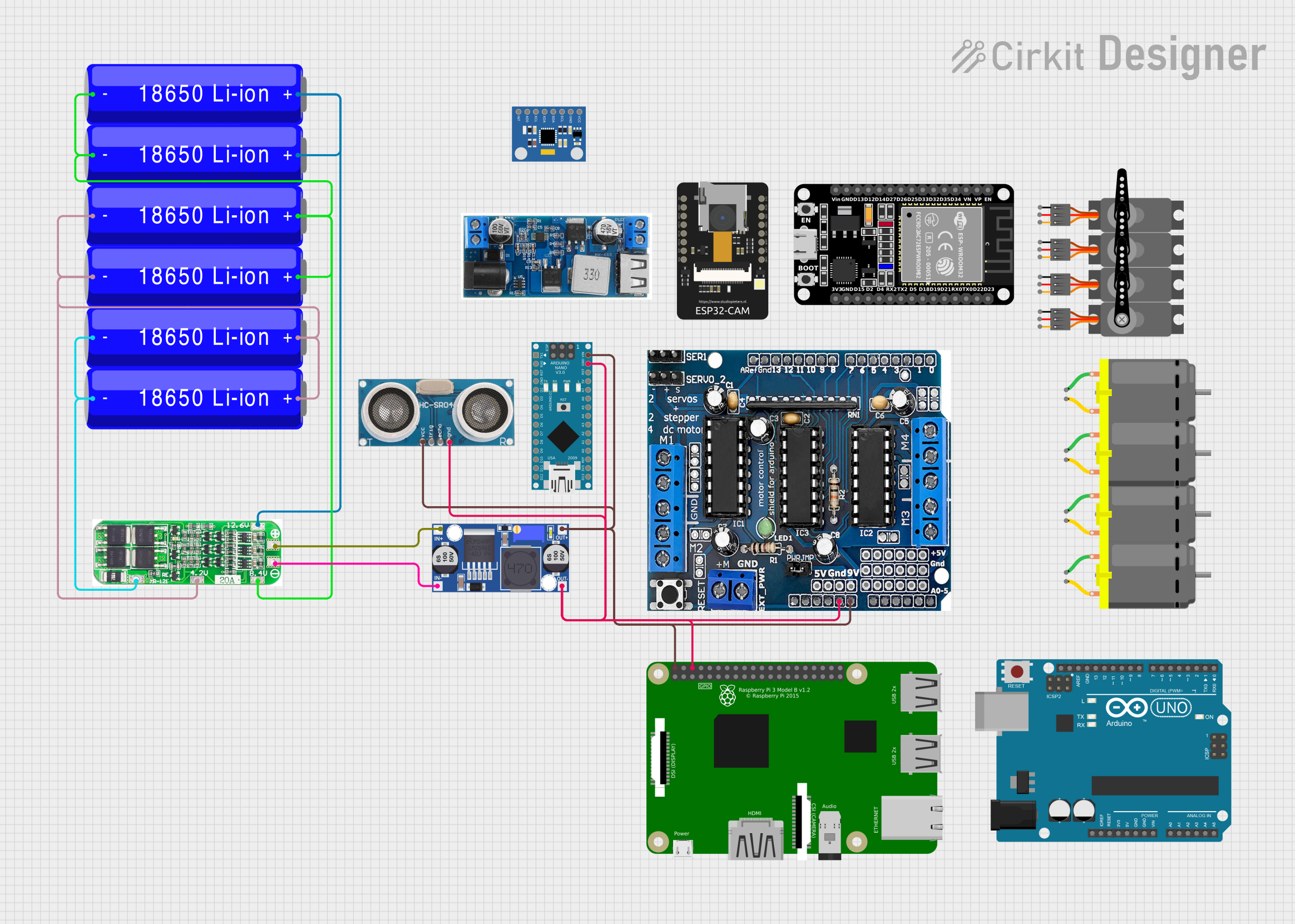
Battery-Powered Robotic System with ESP32, Arduino, and Raspberry Pi
Circuit Documentation
Summary
This document provides a detailed overview of a circuit that includes various microcontrollers, sensors, motors, and power management components. The circuit is designed to interface multiple devices, including an ESP32, Arduino Nano, Raspberry Pi, and several other components, to achieve a complex functionality. The document includes a component list, wiring details, and documented code for the microcontrollers.
Component List
ESP32 (30 pin)
- Description: A powerful microcontroller with Wi-Fi and Bluetooth capabilities.
- Pins: EN, VP, VN, D34, D35, D32, D33, D25, D26, D27, D14, D12, D13, GND, Vin, D23, D22, TX0, RX0, D21, D19, D18, D5, TX2, RX2, D4, D2, D15, 3V3
ESP32 - CAM
- Description: A microcontroller with an integrated camera module.
- Pins: 5V, GND, IO12, IO13, IO15, IO14, IO2, IO4, VOT, VOR, VCC, IO0, IO16, 3V3
Arduino UNO
- Description: A popular microcontroller board based on the ATmega328P.
- Pins: UNUSED, IOREF, Reset, 3.3V, 5V, GND, Vin, A0, A1, A2, A3, A4, A5, SCL, SDA, AREF, D13, D12, D11, D10, D9, D8, D7, D6, D5, D4, D3, D2, D1, D0
Arduino Nano
- Description: A compact version of the Arduino UNO with similar functionality.
- Pins: D1/TX, D0/RX, RESET, GND, D2, D3, D4, D5, D6, D7, D8, D9, D10, D11/MOSI, D12/MISO, VIN, 5V, A7, A6, A5, A4, A3, A2, A1, A0, AREF, 3V3, D13/SCK
L293D
- Description: A quadruple high-current half-H driver for driving motors.
- Pins: 5V, GND, +, Servo1, Servo2, RX/DO, TX/D1, 9V, A0, A1, A2, A3, A4/SDA, A5/SCL, VIN, 3.3V, RESET, D2, D3, D4, D5, D6, D7, D8, D9, D10, D11, D12, D13
Buck Converter
- Description: A DC-DC converter that steps down voltage.
- Pins: IN+, IN-, OUT+, OUT-
24/12v Buck
- Description: A DC-DC converter for stepping down voltage from 24V or 12V to 5V.
- Pins: VIN+, VIN-, 5V, GND
MPU6050 Accelerometer + Gyroscope
- Description: A sensor module for measuring acceleration and gyroscopic data.
- Pins: INT, AD0, XCL, XDA, SDA, SCL, GND, VCC
3s 20A BMS
- Description: A battery management system for 3-cell Li-ion batteries.
- Pins: DV/GND, 4.2V, 8.4V, 12.6V, +, -
18650 Li-ion Battery
- Description: A rechargeable lithium-ion battery.
- Pins: -, +
DC Motor
- Description: A motor that runs on direct current.
- Pins: pin 1, pin 2
Servo
- Description: A motor with a feedback mechanism for precise control.
- Pins: GND, VCC, PWM
Ultrasonic Sensor
- Description: A sensor for measuring distance using ultrasonic waves.
- Pins: +VCC, Trigger, Echo, GND
Raspberry Pi 3B
- Description: A single-board computer with various I/O capabilities.
- Pins: 1, 3, 5, 7, 9, 11, 13, 15, 17, 21, 23, 25, 27, 29, 33, 37, 39, 40, 38, 36, 34, 32, 30, 26, 24, 22, 20, 18, 16, 14, 12, 10, 8, 6, 4, 2(5V), 19, 28, 31, 35
Wiring Details
L293D
- VIN: Connected to +VCC of Ultrasonic Sensor, VIN of Arduino Nano, 2(5V) of Raspberry Pi 3B, OUT+ of Buck Converter
- GND: Connected to GND of Ultrasonic Sensor, GND of Arduino Nano, 6 of Raspberry Pi 3B, OUT- of Buck Converter
Ultrasonic Sensor
- +VCC: Connected to VIN of L293D
- GND: Connected to GND of L293D
Arduino Nano
- VIN: Connected to VIN of L293D
- GND: Connected to GND of L293D
Raspberry Pi 3B
- 2(5V): Connected to VIN of L293D
- 6: Connected to GND of L293D
Buck Converter
- OUT+: Connected to VIN of L293D
- OUT-: Connected to GND of L293D
- IN+: Connected to + of 3s 20A BMS
- IN-: Connected to - of 3s 20A BMS
3s 20A BMS
- +: Connected to IN+ of Buck Converter
- -: Connected to IN- of Buck Converter
- DV/GND: Connected to - of 18650 Li-ion Battery
- 4.2V: Connected to + of 18650 Li-ion Battery
- 8.4V: Connected to + of 18650 Li-ion Battery
- 12.6V: Connected to + of 18650 Li-ion Battery
18650 Li-ion Battery
- -: Connected to DV/GND of 3s 20A BMS
- +: Connected to 4.2V, 8.4V, 12.6V of 3s 20A BMS
Documented Code
Arduino UNO
void setup() {
  // put your setup code here, to run once:

}

void loop() {
  // put your main code here, to run repeatedly:

}
Arduino Nano
void setup() {
  // put your setup code here, to run once:

}

void loop() {
  // put your main code here, to run repeatedly:

}
This documentation provides a comprehensive overview of the circuit, including the components used, their wiring details, and the code for the microcontrollers.