
Arduino-Controlled Temperature Monitoring and Fan Activation System
View and Edit Project In Cirkit Designer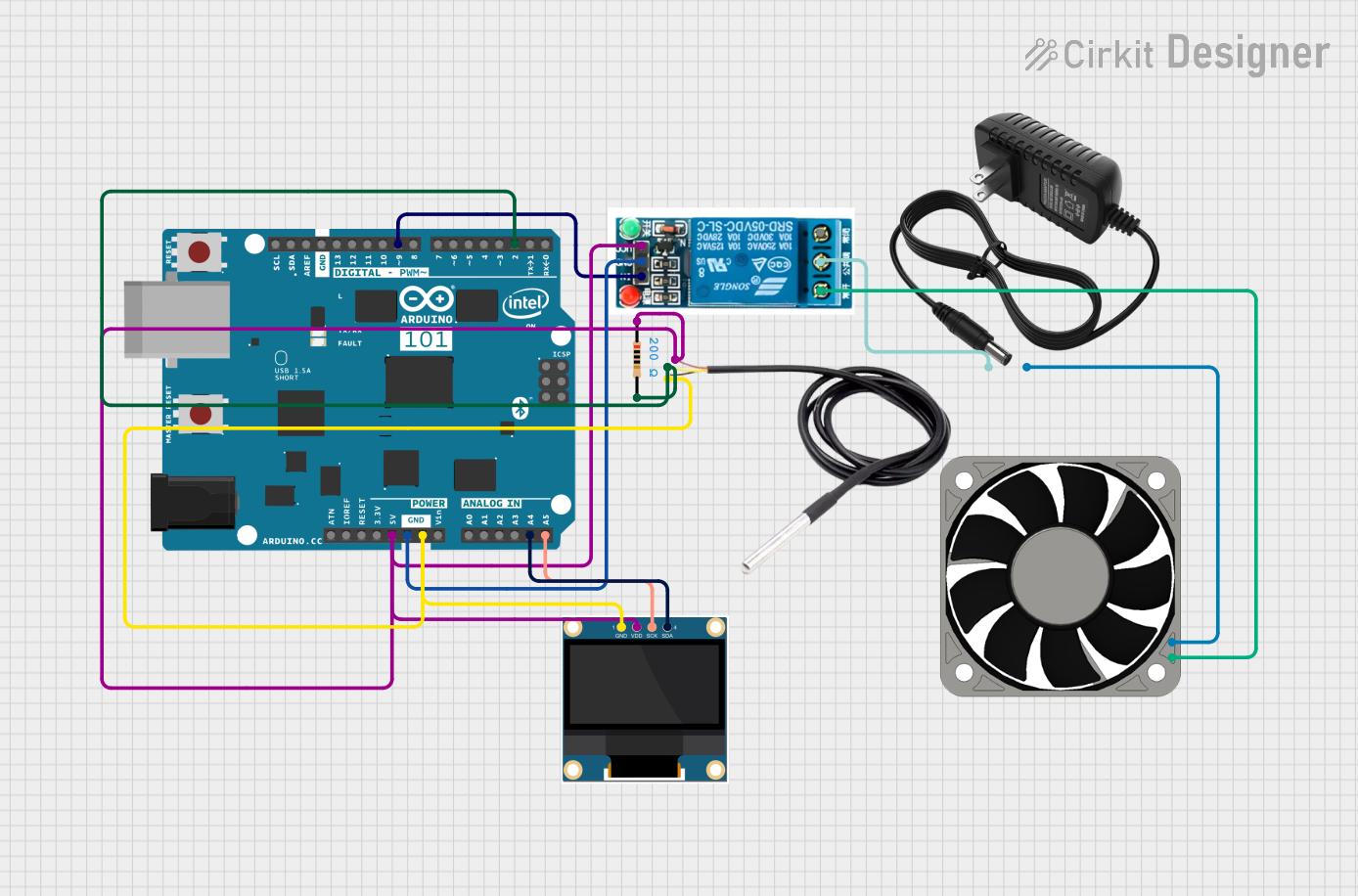
Circuit Documentation
Summary
The circuit in question is designed to interface an Arduino 101 with a variety of components including a 5V relay, a DS18B20 temperature sensor, a 0.96" OLED display, and a 40mm 12V fan. The circuit is powered by a 12V power supply. The Arduino 101 controls the relay, which in turn controls the power to the fan. The temperature sensor provides input to the Arduino, which can be displayed on the OLED. The relay's operation is likely tied to the temperature readings, allowing for automated control of the fan based on the temperature data.
Component List
Arduino 101
- Microcontroller board based on the Intel Curie module.
- Provides I/O pins for interfacing with various components and sensors.
- Capable of PWM output, I2C communication, and analog input.
5V Relay
- An electromechanical switch that allows a low-power signal to control a higher power circuit.
- Has a Normally Open (NO) and a Normally Closed (NC) contact, along with a common terminal.
DS18B20 Temperature Sensor
- A digital temperature sensor that provides 9-bit to 12-bit Celsius temperature measurements.
- Communicates over a 1-Wire bus that requires only one data line (and ground) for communication.
0.96" OLED Display
- A small display that can show text and graphics in monochrome.
- Interfaces with the Arduino via I2C communication.
40mm 12V Fan
- A standard cooling fan used in electronics and computer applications.
- Operates on 12V DC power.
12V Power Supply
- Provides the necessary 12V DC power to the fan and the relay's common terminal.
Resistor
- A 200 Ohm resistor used likely for pull-up or pull-down purposes in the circuit.
Wiring Details
Arduino 101
A5/SCLconnected to OLEDSCKfor I2C clock.A4/SDAconnected to OLEDSDAfor I2C data.D9 PWMconnected to RelayInfor relay control.D2connected to DS18B20signalthrough a 200 Ohm resistor.5Vconnected to DS18B20vcc, RelayVCC, and OLEDVDD.GNDconnected to DS18B20GND, RelayGND, and OLEDGND.
5V Relay
Normally Openconnected to Fan+12V.Common terminalconnected to 12V Power Supply+.Incontrolled by ArduinoD9 PWM.GNDshared with Arduino.VCCconnected to Arduino5V.
DS18B20 Temperature Sensor
signalconnected to ArduinoD2through a 200 Ohm resistor.GNDshared with Arduino.vccconnected to Arduino5V.
0.96" OLED Display
GNDshared with Arduino.VDDconnected to Arduino5V.SCKconnected to ArduinoA5/SCLfor I2C clock.SDAconnected to ArduinoA4/SDAfor I2C data.
40mm 12V Fan
+12Vconnected to RelayNormally Open.-12Vconnected to 12V Power Supply-.
12V Power Supply
+connected to RelayCommon terminal.-connected to Fan-12V.
Resistor
pin1connected to DS18B20vcc.pin2connected to DS18B20signaland ArduinoD2.
Documented Code
No code was provided for the microcontroller. The expected code would handle reading temperature data from the DS18B20 sensor, controlling the relay based on temperature thresholds, and displaying the temperature on the OLED screen. It would also include setup for I2C communication and possibly debounce logic for the relay control.