
Circuit Documentation
Summary of the Circuit
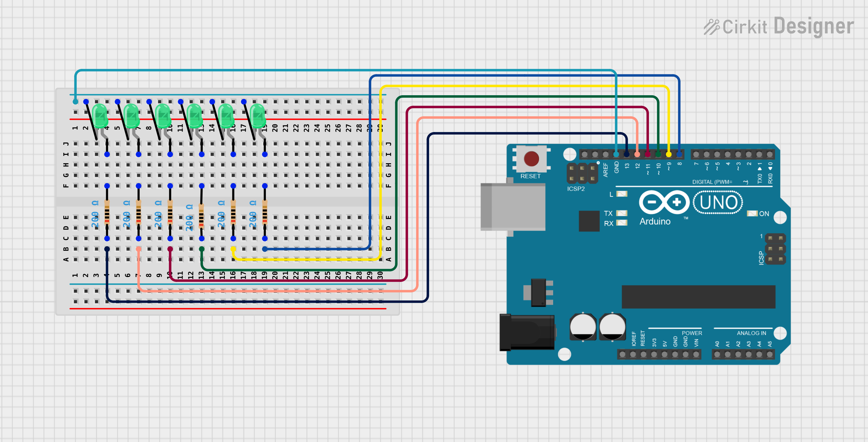
This circuit consists of an Arduino UNO microcontroller used to control six green LEDs. Each LED is connected in series with a 200 Ohm resistor. The LEDs are connected to the digital pins D13, D12, D11, D10, D9, and D8 of the Arduino UNO. The purpose of this circuit is to demonstrate the ability to turn on and off multiple LEDs in a sequence, creating a blinking effect.
Component List
Arduino UNO
- Description: A microcontroller board based on the ATmega328P.
- Pins: UNUSED, IOREF, Reset, 3.3V, 5V, GND, Vin, A0-A5, SCL, SDA, AREF, D0-D13
LEDs (Green)
- Description: Standard two-pin green LEDs.
- Pins: Anode, Cathode
Resistors
- Description: 200 Ohm resistors used to limit current to the LEDs.
- Resistance: 200 Ohms
Wiring Details
Arduino UNO
- D13: Connected to a 200 Ohm resistor leading to an LED.
- D12: Connected to a 200 Ohm resistor leading to an LED.
- D11: Connected to a 200 Ohm resistor leading to an LED.
- D10: Connected to a 200 Ohm resistor leading to an LED.
- D9: Connected to a 200 Ohm resistor leading to an LED.
- D8: Connected to a 200 Ohm resistor leading to an LED.
- GND: Connected to the cathodes of all six LEDs.
LEDs (Green)
- Anode: Each anode is connected to a 200 Ohm resistor.
- Cathode: All cathodes are connected to the GND pin on the Arduino UNO.
Resistors
- One side (pin1) is connected to an Arduino UNO digital pin (D13, D12, D11, D10, D9, or D8).
- The other side (pin2) is connected to the anode of a green LED.
Documented Code
/*
 * Arduino Sketch to control six green LEDs with pull-up resistors.
 * The LEDs are connected to digital pins D13, D12, D11, D10, D9, and D8.
 * Each LED is connected in series with a 200 Ohm resistor.
 */

void setup() {
  // Set pin modes for LED pins
  pinMode(13, OUTPUT);
  pinMode(12, OUTPUT);
  pinMode(11, OUTPUT);
  pinMode(10, OUTPUT);
  pinMode(9, OUTPUT);
  pinMode(8, OUTPUT);

  // Initialize all LEDs to be off
  digitalWrite(13, HIGH);
  digitalWrite(12, HIGH);
  digitalWrite(11, HIGH);
  digitalWrite(10, HIGH);
  digitalWrite(9, HIGH);
  digitalWrite(8, HIGH);
}

void loop() {
  // Example: Blink all LEDs
  digitalWrite(13, LOW); // Turn on LED connected to D13
  digitalWrite(12, LOW); // Turn on LED connected to D12
  digitalWrite(11, LOW); // Turn on LED connected to D11
  digitalWrite(10, LOW); // Turn on LED connected to D10
  digitalWrite(9, LOW); // Turn on LED connected to D9
  digitalWrite(8, LOW); // Turn on LED connected to D8
  delay(1000); // Wait for 1 second

  digitalWrite(13, HIGH); // Turn off LED connected to D13
  digitalWrite(12, HIGH); // Turn off LED connected to D12
  digitalWrite(11, HIGH); // Turn off LED connected to D11
  digitalWrite(10, HIGH); // Turn off LED connected to D10
  digitalWrite(9, HIGH); // Turn off LED connected to D9
  digitalWrite(8, HIGH); // Turn off LED connected to D8
  delay(1000); // Wait for 1 second
}
This code is designed to run on the Arduino UNO microcontroller. It initializes the digital pins D13 to D8 as outputs and sets them to HIGH, which turns off the connected LEDs due to the common ground configuration. In the loop function, the code toggles the state of each LED, creating a blinking effect with a 1-second interval.