
Coreless Motor Clock with Adjustable Speed Control using IRFZ44N MOSFET
View and Edit Project In Cirkit Designer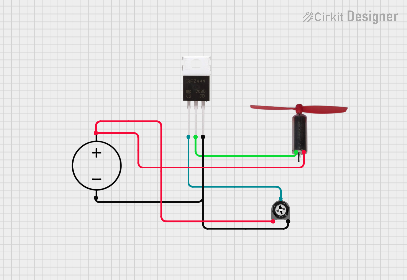
Circuit Documentation
Summary
This circuit is designed to control a coreless motor using a MOSFET and a trimmer potentiometer. The circuit is powered by a DC power source. The trimmer potentiometer is used to adjust the gate voltage of the MOSFET, which in turn controls the current flowing through the motor.
Component List
Coreless Motor Clock
- Pins: +, -
- Description: A coreless motor used for precise clock mechanisms.
- Purpose in Circuit: The main load driven by the circuit.
IRFZ44N
- Pins: Gate, Drain, Source
- Description: A N-channel MOSFET.
- Purpose in Circuit: Acts as a switch to control the motor.
Trimmer Potentiometer
- Pins: leg1, wiper, leg2
- Description: A variable resistor with a resistance of 10k Ohms.
- Purpose in Circuit: Adjusts the gate voltage of the MOSFET.
DC Power Source
- Pins: Ground, Positive
- Description: Provides the necessary power for the circuit.
- Purpose in Circuit: Supplies power to the motor and the control circuitry.
Wiring Details
Coreless Motor Clock
- Pin + is connected to Drain of the IRFZ44N.
- Pin - is connected to Positive of the DC Power Source and leg1 of the Trimmer Potentiometer.
IRFZ44N
- Drain is connected to Pin + of the Coreless Motor Clock.
- Gate is connected to wiper of the Trimmer Potentiometer.
- Source is connected to Ground of the DC Power Source and leg2 of the Trimmer Potentiometer.
Trimmer Potentiometer
- leg1 is connected to Positive of the DC Power Source and Pin - of the Coreless Motor Clock.
- wiper is connected to Gate of the IRFZ44N.
- leg2 is connected to Ground of the DC Power Source and Source of the IRFZ44N.
DC Power Source
- Positive is connected to leg1 of the Trimmer Potentiometer and Pin - of the Coreless Motor Clock.
- Ground is connected to Source of the IRFZ44N and leg2 of the Trimmer Potentiometer.
Code
No microcontroller code is provided for this circuit.