
Arduino Nano Controlled Line Following Robot with L293D Motor Driver
View and Edit Project In Cirkit Designer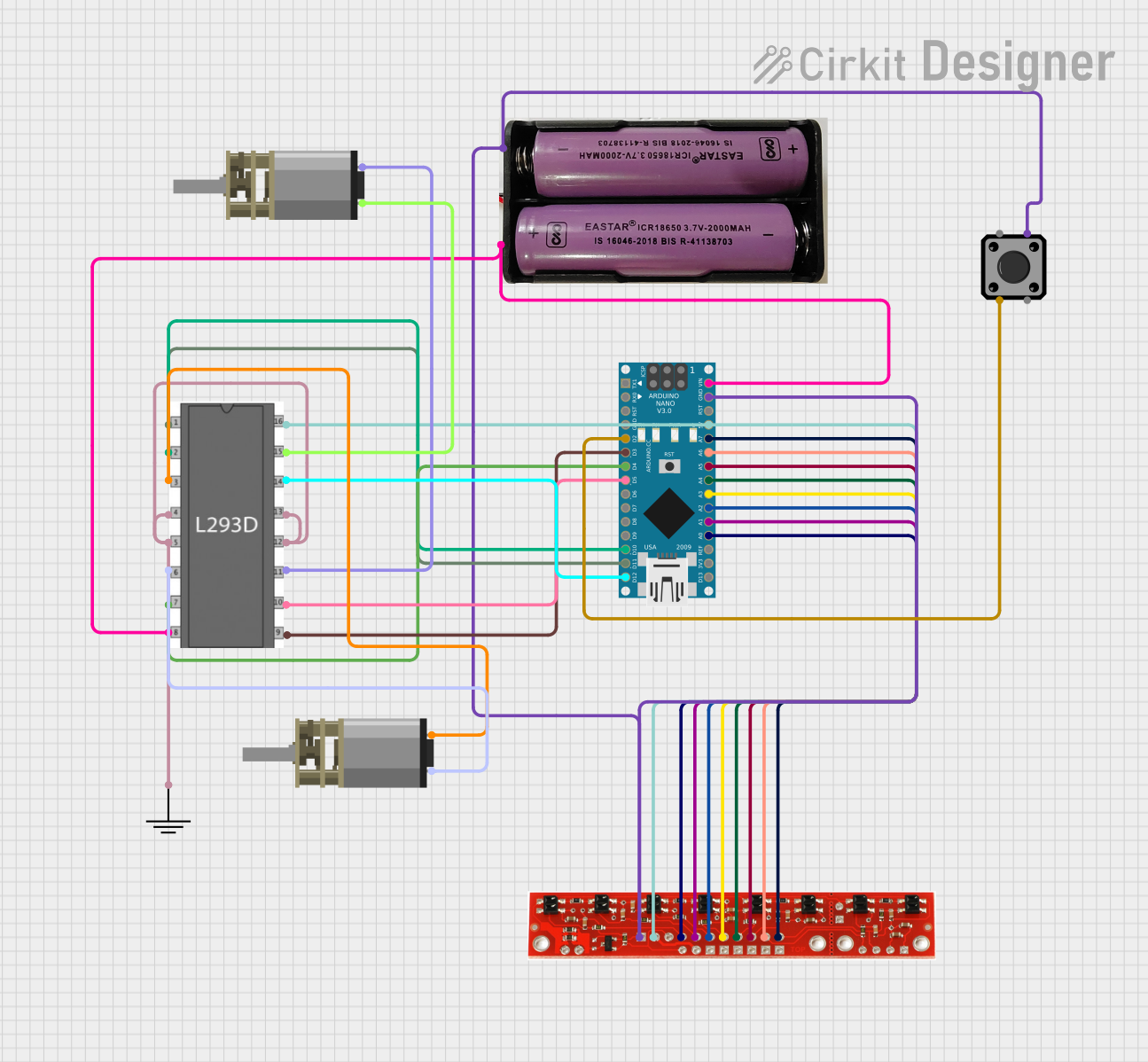
Circuit Documentation
Summary
This circuit is designed around an Arduino Nano microcontroller and includes a variety of components such as a tactile switch, an L293D motor driver, a line sensor, two DC mini metal gear motors, and a power source of 7.4 volts. The circuit is likely intended for a small robotic application, given the inclusion of motors and a line sensor, which could be used for line following robots. The Arduino Nano serves as the central processing unit, interfacing with the line sensor for input and controlling the motors through the motor driver. The tactile switch may serve as a manual input for starting or stopping the robot.
Component List
Arduino Nano
- Microcontroller board based on the ATmega328P
- It has a variety of digital and analog I/O pins.
Tactile Switch Buttons - 12mm Square
- A simple push-button switch for user input.
L293D Motor Driver
- A motor driver IC capable of driving two motors simultaneously.
7.4V Battery
- Power source for the circuit.
Line Sensor
- An array sensor used to detect lines or contrasts on the ground.
DC Mini Metal Gear Motor (x2)
- Small DC motors with gear reduction for increased torque.
GND (Common Ground)
- A reference point for all voltage measurements and a return path for electric current.
Wiring Details
Arduino Nano
- D2 connected to Tactile Switch Button pin 3
- D3 connected to L293D Motor Driver enable 2
- D4 connected to L293D Motor Driver input 2
- D5 connected to L293D Motor Driver input 3
- D10 connected to L293D Motor Driver input 1
- D11/MOSI connected to L293D Motor Driver enable 1
- D12/MISO connected to L293D Motor Driver output 4
- VIN connected to 7.4V Battery positive and L293D Motor Driver vs
- GND connected to Tactile Switch Button pin 2, 7.4V Battery negative, Line Sensor GND
- 5V connected to L293D Motor Driver vss and Line Sensor +5v
- A0-A7 connected to Line Sensor pins 1-8 respectively
Tactile Switch Buttons - 12mm Square
- Pin 3 connected to Arduino Nano D2
- Pin 2 connected to common GND
L293D Motor Driver
- Enable 1 connected to Arduino Nano D11/MOSI
- Input 1 connected to Arduino Nano D10
- Output 1 connected to DC Mini Metal Gear Motor IN2
- Enable 2 connected to Arduino Nano D3
- Input 2 connected to Arduino Nano D4
- Output 2 connected to DC Mini Metal Gear Motor IN1
- Input 3 connected to Arduino Nano D5
- Output 3 connected to DC Mini Metal Gear Motor IN2
- Input 4 connected to DC Mini Metal Gear Motor IN1
- Output 4 connected to Arduino Nano D12/MISO
- Vs connected to 7.4V Battery positive and Arduino Nano VIN
- Vss connected to Arduino Nano 5V
- GND connected to common GND
7.4V Battery
- Positive (+) connected to Arduino Nano VIN and L293D Motor Driver vs
- Negative (-) connected to common GND
Line Sensor
- Pins 1-8 connected to Arduino Nano A0-A7 respectively
- +5v connected to Arduino Nano 5V
- GND connected to common GND
DC Mini Metal Gear Motor
- IN1 connected to L293D Motor Driver output 2
- IN2 connected to L293D Motor Driver output 1
DC Mini Metal Gear Motor (Second Motor)
- IN1 connected to L293D Motor Driver input 4
- IN2 connected to L293D Motor Driver output 3
GND (Common Ground)
- GND connected to all components requiring a ground connection.
Documented Code
Arduino Nano Code (sketch.ino)
void setup() {
  // put your setup code here, to run once:

}

void loop() {
  // put your main code here, to run repeatedly:

}
Additional Notes (documentation.txt)
No additional code documentation was provided.