
ESP32-Based Smart Irrigation and Environmental Monitoring System
View and Edit Project In Cirkit Designer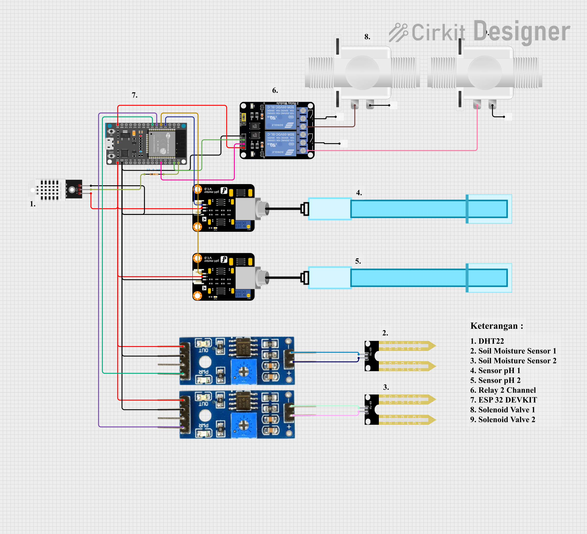
Circuit Documentation
Summary
This circuit is designed to interface various sensors and actuators with an ESP32 Devkit V1 microcontroller. The sensors include a DHT22 temperature and humidity sensor, a YL-69 soil moisture sensor, and two PH meters. Actuators in the circuit are two plastic solenoid valves controlled via a 2-channel relay module. The ESP32 Devkit V1 serves as the central processing unit, reading sensor data and controlling the solenoid valves based on predefined conditions. The circuit is powered by the 3V3 output from the ESP32, which also provides ground connections to the various components.
Component List
DHT22
- Temperature and Humidity Sensor
- Pins: +, Out, -
Plastic Solenoid Valve
- Actuator for controlling fluid flow
- Pins: pin1, pin2
ESP32 Devkit V1
- Microcontroller with WiFi capability
- Pins: 3V3, GND, D15, D2, D4, RX2, TX2, D5, D18, D19, D21, RX0, TX0, D22, D23, EN, VP, VN, D34, D35, D32, D33, D25, D26, D27, D14, D12, D13, VIN
Resistor
- Passive component used to limit current or divide voltages
- Resistance: 10000 Ohms
YL-69 Sonda
- Soil moisture sensor
- Pins: +, -
Kabel
- Wire or cable for making electrical connections
PH Meter
- Sensor for measuring the pH level of a solution
- Pins: Signal, VCC, GND
Soil Moisture Module
- Sensor for detecting the moisture level in soil
- Pins: positive, negative, Analog, Digital, Ground, VCC
Relay Module 2 Channel
- Module for controlling high power devices using low power signals
- Pins: GND, IN1, IN2, VCC, NC1, COM, NO1, NC2, NO2
Wiring Details
DHT22
+to ESP32 3V3Outto ESP32 D23 through a 10k Ohm resistor-to ESP32 GND
Plastic Solenoid Valve (1st instance)
pin1to Relay Module NO1pin2to Kabel 1 (presumably connected to power supply)
Plastic Solenoid Valve (2nd instance)
pin1to Relay Module NO2pin2to Kabel 1 (presumably connected to power supply)
ESP32 Devkit V1
3V3to VCC of DHT22, PH Meters, and Soil Moisture ModulesGNDto GND of DHT22, PH Meters, Relay Module, and Soil Moisture ModulesD34to Signal of PH Meter (1st instance)D35to Signal of PH Meter (2nd instance)D32to Analog of Soil Moisture Module (1st instance)D33to Analog of Soil Moisture Module (2nd instance)D22to IN1 of Relay ModuleD21to IN2 of Relay ModuleVINto VCC of Relay Module
YL-69 Sonda (1st instance)
+to positive of Soil Moisture Module (2nd instance)-to negative of Soil Moisture Module (2nd instance)
YL-69 Sonda (2nd instance)
+to positive of Soil Moisture Module (1st instance)-to negative of Soil Moisture Module (1st instance)
PH Meter (1st instance)
Signalto ESP32 D34VCCto ESP32 3V3GNDto ESP32 GND
PH Meter (2nd instance)
Signalto ESP32 D35VCCto ESP32 3V3GNDto ESP32 GND
Soil Moisture Module (1st instance)
positiveto YL-69 Sonda (2nd instance) +negativeto YL-69 Sonda (2nd instance) -Analogto ESP32 D32VCCto ESP32 3V3Groundto ESP32 GND
Soil Moisture Module (2nd instance)
positiveto YL-69 Sonda (1st instance) +negativeto YL-69 Sonda (1st instance) -Analogto ESP32 D33VCCto ESP32 3V3Groundto ESP32 GND
Relay Module 2 Channel
GNDto ESP32 GNDIN1to ESP32 D22IN2to ESP32 D21VCCto ESP32 VINNO1to Plastic Solenoid Valve (1st instance) pin1NO2to Plastic Solenoid Valve (2nd instance) pin1COMto Kabel 1 (presumably connected to power supply)
Documented Code
No code was provided for the microcontroller. The expected functionality would include reading sensor data from the DHT22, PH Meters, and Soil Moisture Modules, and controlling the solenoid valves via the relay module based on sensor inputs and programmed logic. The code would likely involve initializing the sensors, reading their outputs, and using digital outputs to control the relay module.