
Arduino Mega 2560 Controlled LED Display with Pushbuttons and Buzzer
View and Edit Project In Cirkit Designer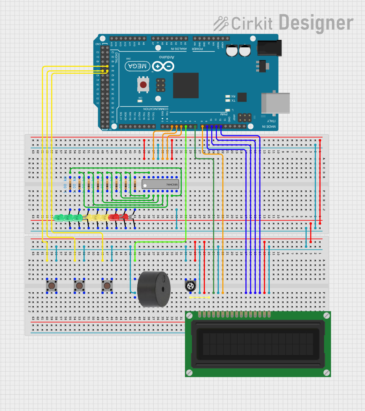
Circuit Documentation
Summary
This document provides a detailed overview of a circuit that includes various components such as pushbuttons, LEDs, a buzzer, a trimmer potentiometer, an LCD display, an Arduino Mega 2560, and a 74HC595 shift register. The circuit is designed to interface these components with the Arduino Mega 2560, allowing for control and interaction through the microcontroller.
Component List
Pushbutton
- Pins: Pin 1 (in), Pin 2 (in), Pin 3 (out), Pin 4 (out)
- Description: A simple pushbutton used for user input.
LCD Display (16 pin)
- Pins: VSS, VDD, VO, RS, R_W, E, DB0, DB1, DB2, DB3, DB4, DB5, DB6, DB7, A, K
- Description: A 16-pin LCD display for visual output.
Arduino Mega 2560
- Pins: IOREF, RESET, 3V3, 5V, GND, VIN, A0-A15, D0-D53, SDA, SCL, AREF
- Description: A microcontroller board based on the ATmega2560.
Buzzer
- Pins: PIN, GND
- Description: A buzzer for audio output.
74HC595
- Pins: Q0-Q7, GND, VCC, DS (DATA), OE (Enable), ST_CP (RCLK), SH_CP (SRCLK), MR (SRCLR), Q7' (QH)
- Description: An 8-bit serial-in, serial or parallel-out shift register.
LED: Two Pin (green)
- Pins: cathode, anode
- Description: A green LED for visual indication.
LED: Two Pin (red)
- Pins: cathode, anode
- Description: A red LED for visual indication.
LED: Two Pin (yellow)
- Pins: cathode, anode
- Description: A yellow LED for visual indication.
Resistor
- Pins: pin1, pin2
- Description: A resistor with a resistance of 1000 Ohms.
Trimmer Potentiometer
- Pins: leg1, wiper, leg2
- Description: A trimmer potentiometer with a resistance of 10000 Ohms.
Wiring Details
Pushbutton
Pin 2 (in) connected to GND.
Pin 4 (out) connected to Arduino Mega 2560 D44.
Pin 2 (in) connected to GND.
Pin 4 (out) connected to Arduino Mega 2560 D45.
Pin 2 (in) connected to GND.
Pin 4 (out) connected to Arduino Mega 2560 D46.
LCD Display (16 pin)
- No specific wiring details provided.
Arduino Mega 2560
- D2 PWM connected to 74HC595 DS (DATA).
- D3 PWM connected to 74HC595 ST_CP (RCLK).
- D4 PWM connected to 74HC595 SH_CP (SRCLK).
- D5 PWM connected to Buzzer PIN.
- D44 connected to Pushbutton Pin 4 (out).
- D45 connected to Pushbutton Pin 4 (out).
- D46 connected to Pushbutton Pin 4 (out).
Buzzer
- GND connected to GND.
- PIN connected to Arduino Mega 2560 D5 PWM.
74HC595
- GND connected to GND.
- OE (Enable) connected to GND.
- MR (SRCLR) connected to VCC.
- VCC connected to VCC.
- Q0 connected to Resistor pin2.
- Q1 connected to Resistor pin2.
- Q2 connected to Resistor pin2.
- Q3 connected to Resistor pin2.
- Q4 connected to Resistor pin2.
- Q5 connected to Resistor pin2.
- Q6 connected to Resistor pin2.
- Q7 connected to Resistor pin2.
- DS (DATA) connected to Arduino Mega 2560 D2 PWM.
- ST_CP (RCLK) connected to Arduino Mega 2560 D3 PWM.
- SH_CP (SRCLK) connected to Arduino Mega 2560 D4 PWM.
LED: Two Pin (green)
- cathode connected to GND.
- anode connected to Resistor pin1.
LED: Two Pin (red)
- cathode connected to GND.
- anode connected to Resistor pin1.
LED: Two Pin (yellow)
- cathode connected to GND.
- anode connected to Resistor pin1.
Resistor
- pin1 connected to LED anode.
- pin2 connected to 74HC595 Q0-Q7.
Trimmer Potentiometer
- leg1 connected to VCC.
- wiper connected to Arduino Mega 2560.
- leg2 connected to GND.
Documented Code
Arduino Mega 2560 Code
void setup() {
  // put your setup code here, to run once:

}

void loop() {
  // put your main code here, to run repeatedly:

}
This code is a basic template for the Arduino Mega 2560. The setup() function is used to initialize any settings, and the loop() function contains the main code that runs repeatedly.