
Circuit Documentation
Summary
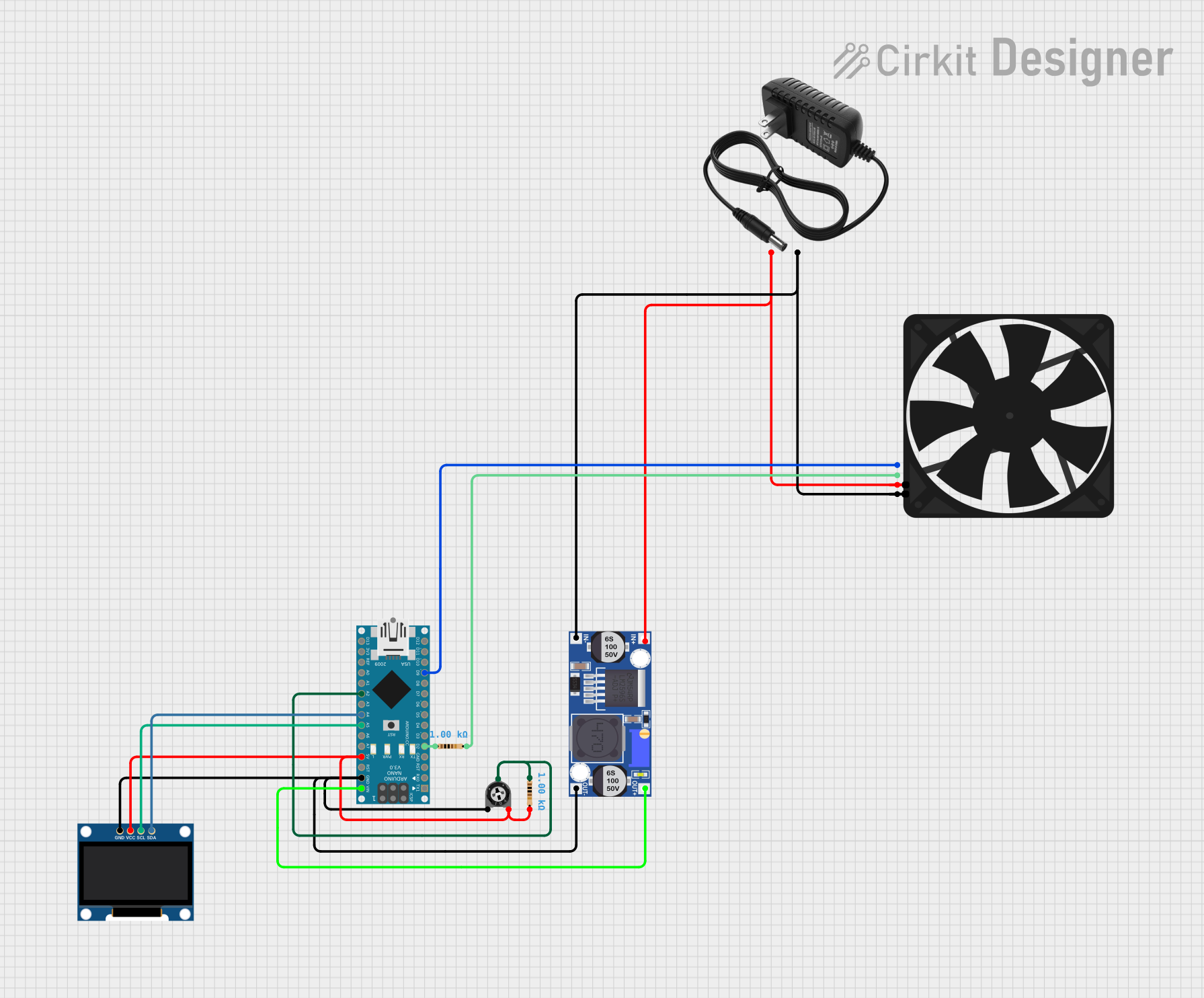
This circuit is designed around an Arduino Nano microcontroller and includes a variety of components that interact with the microcontroller to perform specific functions. The circuit features a PWM Fan controlled by the Arduino, a trimmer potentiometer for adjustable input, a buck converter to step down voltage, an I2C OLED display for user interface, and resistors for current limiting and signal conditioning. The Arduino Nano is powered through a buck converter connected to a 12V power supply, ensuring a stable 5V supply to the microcontroller and other components.
Component List
Arduino Nano
- Microcontroller board based on the ATmega328P
- It has a variety of digital and analog I/O pins.
Trimmer Potentiometer
- Adjustable resistor with a 10k Ohm value
- Used for providing an adjustable voltage input.
Resistor (1k Ohm)
- Fixed resistor with a 1k Ohm value
- Used for current limiting and signal conditioning.
PWM Fan
- A fan with a Pulse Width Modulation (PWM) control input
- Allows for speed control via the PWM signal from the Arduino Nano.
Buck Converter
- A DC-DC converter that steps down voltage from a higher level to a lower level
- Provides a stable power supply to the Arduino Nano and other components.
12V Power Supply
- Provides the input voltage to the buck converter
- Powers the PWM Fan directly.
I2C OLED 128x64
- An OLED display with I2C communication interface
- Used for displaying data and information to the user.
Wiring Details
Arduino Nano
D2connected to one end of a 1k Ohm resistorD9connected to the PWM input of the PWM FanVINconnected to theOUT+of the Buck ConverterGNDconnected to the common ground net5Vconnected to theVCCof the I2C OLED and one end of the trimmer potentiometerA5connected to theSCKof the I2C OLEDA4connected to theSDAof the I2C OLEDA2connected to the wiper of the trimmer potentiometer
Trimmer Potentiometer
leg1connected to theGNDnetleg2connected to the5Vnetwiperconnected toA2on the Arduino Nano and one end of a 1k Ohm resistor
Resistor (1k Ohm)
- One end connected to
D2on the Arduino Nano - The other end connected to the
wiperof the trimmer potentiometer
PWM Fan
GNDconnected to the common ground net12Vconnected to the+of the 12V power supplyFGconnected to the other end of a 1k Ohm resistorPWMconnected toD9on the Arduino Nano
Buck Converter
IN+connected to the+of the 12V power supplyIN-connected to the common ground netOUT+connected toVINon the Arduino NanoOUT-connected to the common ground net
12V Power Supply
+connected to the12Vof the PWM Fan andIN+of the Buck Converter-connected to the common ground net
I2C OLED 128x64
GNDconnected to the common ground netVCCconnected to the5VnetSCKconnected toA5on the Arduino NanoSDAconnected toA4on the Arduino Nano
Documented Code
void setup() {
  // put your setup code here, to run once:

}

void loop() {
  // put your main code here, to run repeatedly:

}
The provided code is a template for the Arduino Nano with empty setup() and loop() functions. The setup() function is intended for initialization code that runs once when the microcontroller is powered on or reset. The loop() function contains the main code that will run repeatedly, allowing the microcontroller to perform its tasks continuously. Additional code should be added to control the PWM Fan, read the trimmer potentiometer, and update the I2C OLED display based on the circuit's requirements.