ESP32-Based Environmental Monitoring System with Gas, Flame Detection, and Light Intensity Measurement
Circuit Documentation
Summary
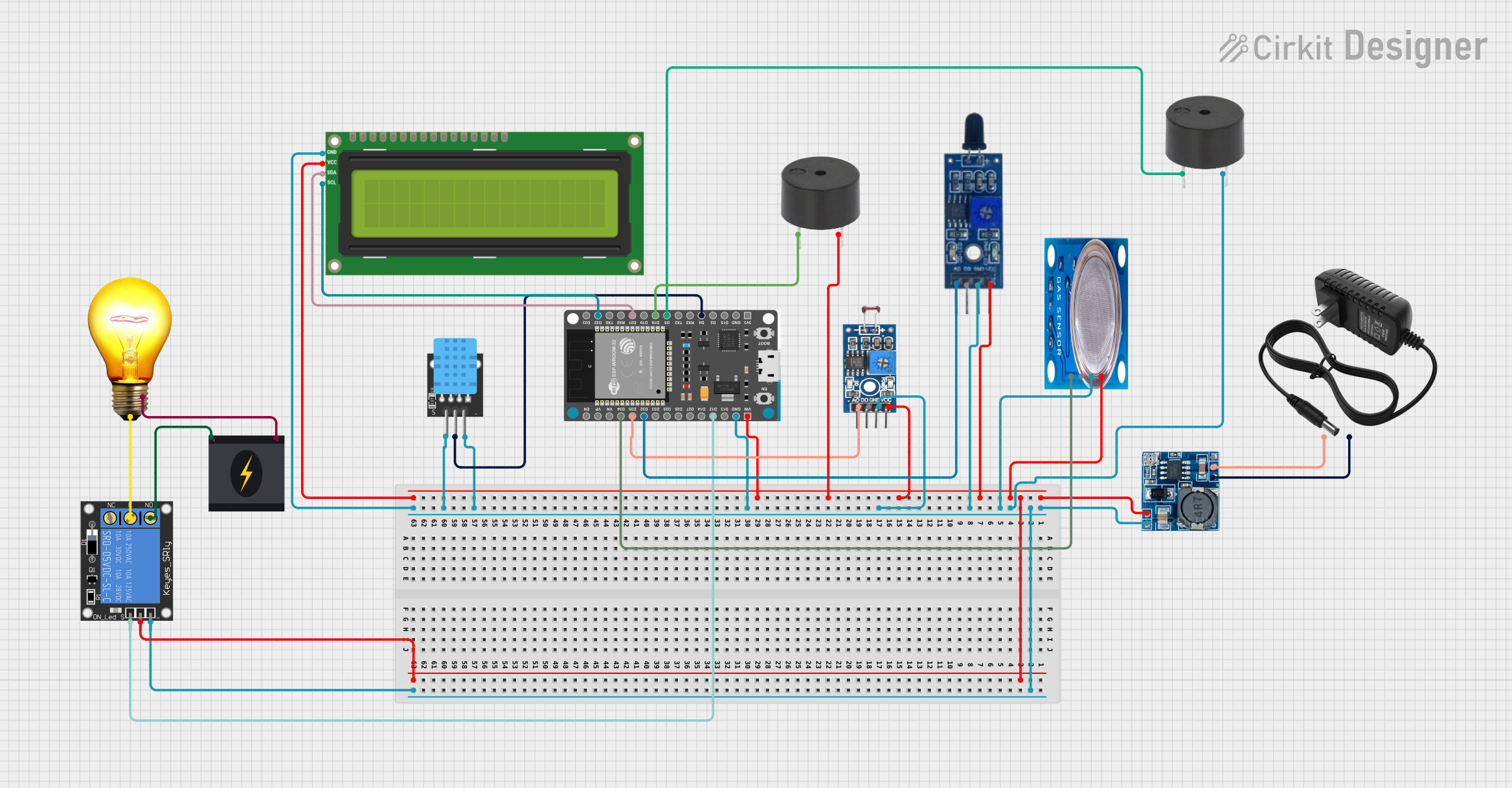
This circuit is designed to monitor environmental parameters such as temperature, humidity, gas concentration, light intensity, and the presence of fire. It utilizes an ESP32 Devkit V1 microcontroller to process sensor data and control peripherals like buzzers, a relay, and an LCD display. The circuit is powered by a step-down module that converts a 12V input to a 5V output, suitable for powering the 5V components. The ESP32 reads sensor data from a DHT11 temperature and humidity sensor, an MQ-5 gas sensor, a photosensitive sensor module for light intensity, and a flame sensor for fire detection. The circuit includes two buzzers for audible alerts and a relay to control an AC bulb. The LCD display provides real-time feedback on the sensor readings.
Component List
- ESP32 Devkit V1: A microcontroller with WiFi capabilities, used for processing sensor data and controlling the circuit's peripherals.
- DHT11: A temperature and humidity sensor.
- MQ-5 Gas Sensor: A sensor for detecting LPG, natural gas, and coal gas.
- Step-down Module: A voltage regulator that steps down the input voltage to 5V.
- 12V Power Supply: Provides the input voltage for the step-down module.
- Buzzer: An audible alert device. There are two buzzers in the circuit.
- 1-Channel Relay (5V 10A): An electrically operated switch that controls the AC bulb.
- 240V Power Source: Supplies power to the AC bulb.
- Flame Sensor: Detects the presence of fire.
- AC Bulb: A standard bulb that operates on 240V AC.
- I2C LCD 16x2 Screen: A display for showing sensor readings and messages.
- Photosensitive Sensor Module Digital Light Intensity Detection: Measures the intensity of ambient light.
Wiring Details
ESP32 Devkit V1
VINconnected to the 5V output of the Step-down Module.GNDconnected to the ground of the Step-down Module.D4connected to the signal pin of the DHT11.D5,D18connected to the PIN of the buzzers.D21(SDA),D22(SCL) connected to the I2C LCD Screen.D34connected to the analog output of the MQ-5 Gas Sensor.D35connected to the analog output of the Photosensitive Sensor Module.D32connected to the analog output of the Flame Sensor.D12connected to the signal pin of the 1-Channel Relay.
DHT11
5Vconnected to the 5V output of the Step-down Module.GNDconnected to the ground of the Step-down Module.Sconnected toD4on the ESP32 Devkit V1.
MQ-5 Gas Sensor
VCCconnected to the 5V output of the Step-down Module.GNDconnected to the ground of the Step-down Module.Analog outconnected toD34on the ESP32 Devkit V1.
Step-down Module
24v IN+not connected in the provided net list.12v IN+connected to the+of the 12V Power Supply.5v OUT+connected to the 5V power rail of the circuit.5v OUT-connected to the ground rail of the circuit.GNDconnected to the-of the 12V Power Supply.
12V Power Supply
+connected to12v IN+on the Step-down Module.-connected toGNDon the Step-down Module.
Buzzer
PINconnected toD5andD18on the ESP32 Devkit V1 (two separate buzzers).GNDconnected to the ground rail of the circuit.
1-Channel Relay (5V 10A)
NCnot connected in the provided net list.signalconnected toD12on the ESP32 Devkit V1.Cconnected toPon the AC Bulb.powerconnected to the 5V power rail of the circuit.NOconnected toLiveon the 240V Power Source.groundconnected to the ground rail of the circuit.
240V Power Source
Liveconnected toNOon the 1-Channel Relay.Neutralconnected toNon the AC Bulb.
Flame Sensor
VCCconnected to the 5V power rail of the circuit.GNDconnected to the ground rail of the circuit.A0connected toD32on the ESP32 Devkit V1.
AC Bulb
Pconnected toCon the 1-Channel Relay.Nconnected toNeutralon the 240V Power Source.
I2C LCD 16x2 Screen
SCLconnected toD22on the ESP32 Devkit V1.SDAconnected toD21on the ESP32 Devkit V1.VCC (5V)connected to the 5V power rail of the circuit.GNDconnected to the ground rail of the circuit.
Photosensitive Sensor Module Digital Light Intensity Detection
Analog Outputconnected toD35on the ESP32 Devkit V1.VCCconnected to the 5V power rail of the circuit.Groundconnected to the ground rail of the circuit.
Documented Code
ESP32 Devkit V1 Code
#include <Wire.h>
#include <LiquidCrystal_I2C.h>
#include "DHT.h"

// Define DHT sensor settings
#define DHTPIN 4       // Connect your DHT sensor to GPIO4 (change if needed)
#define DHTTYPE DHT11  // DHT11 or DHT22, depending on your sensor

DHT dht(DHTPIN, DHTTYPE);  // Initialize the DHT sensor

// Initialize the LCD with the I2C address and dimensions (16x2)
LiquidCrystal_I2C lcd(0x27, 16, 2);

// Define gas sensor, LDR sensor, fire sensor, buzzers, and relay settings
#define GAS_PIN 34          // ESP32 analog pin for gas sensor (change if needed)
#define BUZZER_PIN 5        // Buzzer connected to GPIO5
#define GAS_THRESHOLD 3000  // Threshold for gas sensor (adjust based on your sensor)

#define LDR_PIN 35          // ESP32 analog pin for LDR sensor (change if needed)
#define RELAY_PIN 12        // Relay connected to GPIO12
#define LDR_THRESHOLD 1000  // Threshold for LDR sensor (adjust based on your environment)

#define FIRE_PIN 32         // ESP32 digital pin for fire sensor (change if needed)
#define BUZZER2_PIN 18      // Additional buzzer connected to GPIO13

// Variables to store sensor readings
float humidity;
float temperature;
int gasValue;
int ldrValue;
int fireValue;

void setup() {
  lcd.begin();             // Initialize the LCD
  lcd.backlight();         // Turn on the backlight
  dht.begin();             // Initialize the DHT sensor
  pinMode(GAS_PIN, INPUT); // Set the gas sensor pin as input
  pinMode(LDR_PIN, INPUT); // Set the LDR sensor pin as input
  pinMode(FIRE_PIN, INPUT); // Set the fire sensor pin as input
  pinMode(BUZZER_PIN, OUTPUT); // Set the buzzer pin as output
  pinMode(BUZZER2_PIN, OUTPUT); // Set the second buzzer pin as output
  pinMode(RELAY_PIN, OUTPUT);  // Set the relay pin as output
  lcd.print("Starting..."); // Print a startup message
  delay(2000);             // Wait for 2 seconds
  lcd.clear();             // Clear the display
}

void loop() {
  // Read temperature and humidity from DHT sensor
  humidity = dht.readHumidity();
  temperature = dht.readTemperature();
  gasValue = analogRead(GAS_PIN);  // Read the gas sensor value
  ldrValue = analogRead(LDR_PIN);  // Read the LDR sensor value
  fireValue = digitalRead(FIRE_PIN); // Read the fire sensor value (digital)

  // Check if any readings failed and exit early (to try again).
  if (isnan(humidity) || isnan(temperature)) {
    lcd.setCursor(0, 0);
    lcd.print("Sensor error!");
    return;
  }

  // Display humidity and temperature on the first two rows
  lcd.setCursor(0, 0);
  lcd.print("Hum: ");
  lcd.print(humidity);
  lcd.print("%");

  lcd.setCursor(0, 1);
  lcd.print("Temp: ");
  lcd.print(temperature);
  lcd.print(" C");
  delay(2000);
  lcd.clear();

  // Display gas sensor and LDR sensor values
  lcd