
Arduino UNO Based Water Level Indicator with Multicolor LED Alert and Buzzer
View and Edit Project In Cirkit Designer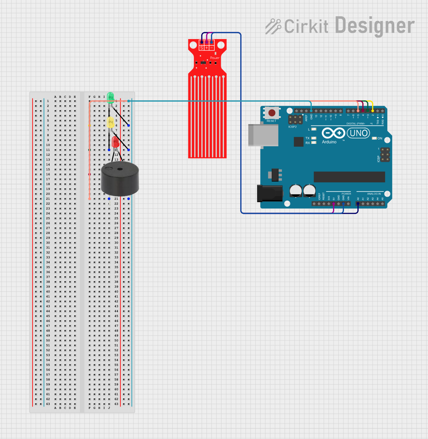
Circuit Documentation
Summary
This circuit is designed to monitor water levels using a water level sensor and provide visual indicators through LEDs and an audible alert using a buzzer. The Arduino UNO serves as the central processing unit, reading the sensor data and controlling the outputs based on predefined thresholds. The water level sensor's signal is read by the Arduino's analog input. Depending on the sensor value, different LEDs will light up, and the buzzer may sound an alert.
Component List
Arduino UNO
- Description: A microcontroller board based on the ATmega328P.
- Purpose: Acts as the central controller for reading sensor data and driving the LEDs and buzzer.
Water Level Sensor
- Description: A sensor that detects the level of water.
- Purpose: Provides analog signal to the Arduino corresponding to the water level.
LED: Two Pin (red)
- Description: A red light-emitting diode.
- Purpose: Serves as an indicator for a specific range of water levels.
LED: Two Pin (green)
- Description: A green light-emitting diode.
- Purpose: Serves as an indicator for a specific range of water levels.
LED: Two Pin (yellow)
- Description: A yellow light-emitting diode.
- Purpose: Serves as an indicator for a specific range of water levels.
Buzzer
- Description: An electronic buzzer.
- Purpose: Provides an audible alert when the water level reaches a critical threshold.
Wiring Details
Arduino UNO
- Digital Pin 2 connected to the cathode of the green LED.
- Digital Pin 3 connected to the cathode of the yellow LED.
- Digital Pin 4 connected to the cathode of the red LED.
- Digital Pin 5 connected to the buzzer PIN.
- Ground (GND) connected to the anodes of all LEDs and the GND of the buzzer.
- 5V output connected to the VCC of the Water Level Sensor.
- Analog Pin A0 connected to the SIG of the Water Level Sensor.
Water Level Sensor
- VCC connected to the 5V output of the Arduino UNO.
- GND connected to the Ground (GND) of the Arduino UNO.
- SIG connected to Analog Pin A0 of the Arduino UNO.
LED: Two Pin (red)
- Cathode connected to Digital Pin 4 of the Arduino UNO.
- Anode connected to Ground (GND) of the Arduino UNO.
LED: Two Pin (green)
- Cathode connected to Digital Pin 2 of the Arduino UNO.
- Anode connected to Ground (GND) of the Arduino UNO.
LED: Two Pin (yellow)
- Cathode connected to Digital Pin 3 of the Arduino UNO.
- Anode connected to Ground (GND) of the Arduino UNO.
Buzzer
- PIN connected to Digital Pin 5 of the Arduino UNO.
- GND connected to Ground (GND) of the Arduino UNO.
Documented Code
const int analogInPin = A0;
int sensorValue = 0;

void setup() {
  // declare pin to be an output:
  pinMode(2, OUTPUT);
  pinMode(3, OUTPUT);
  pinMode(4, OUTPUT);
  pinMode(5, OUTPUT);
  Serial.begin(9600);
}

// the loop routine runs over and over again forever:
void loop() {
  sensorValue = analogRead(analogInPin);
  Serial.print("sensor = ");
  Serial.print(sensorValue);
  Serial.print("\n");
  delay(2);
  if ((sensorValue >= 100) && (sensorValue <= 600)) {
    digitalWrite(2, HIGH);
    delay(100);
  }
  else if ((sensorValue >= 601) && (sensorValue <= 625)) {
    digitalWrite(3, HIGH);
    delay(100);
  }
  else if ((sensorValue >= 626) && (sensorValue <= 700)) {
    digitalWrite(4, HIGH);
    digitalWrite(5, HIGH);
  }
  else {
    digitalWrite(2, LOW);
    digitalWrite(3, LOW);
    digitalWrite(4, LOW);
    digitalWrite(5, LOW);
    delay(100);
  }
}
Filename: sketch.ino
This code continuously reads the analog value from the water level sensor and outputs to the serial monitor. Depending on the value read, it will turn on the green LED for values between 100 and 600, the yellow LED for values between 601 and 625, and both the red LED and the buzzer for values between 626 and 700. If the value is outside these ranges, all outputs are turned off.