
Arduino-Controlled Nutrient and Water Management System with ESP32-CAM and Relay
View and Edit Project In Cirkit Designer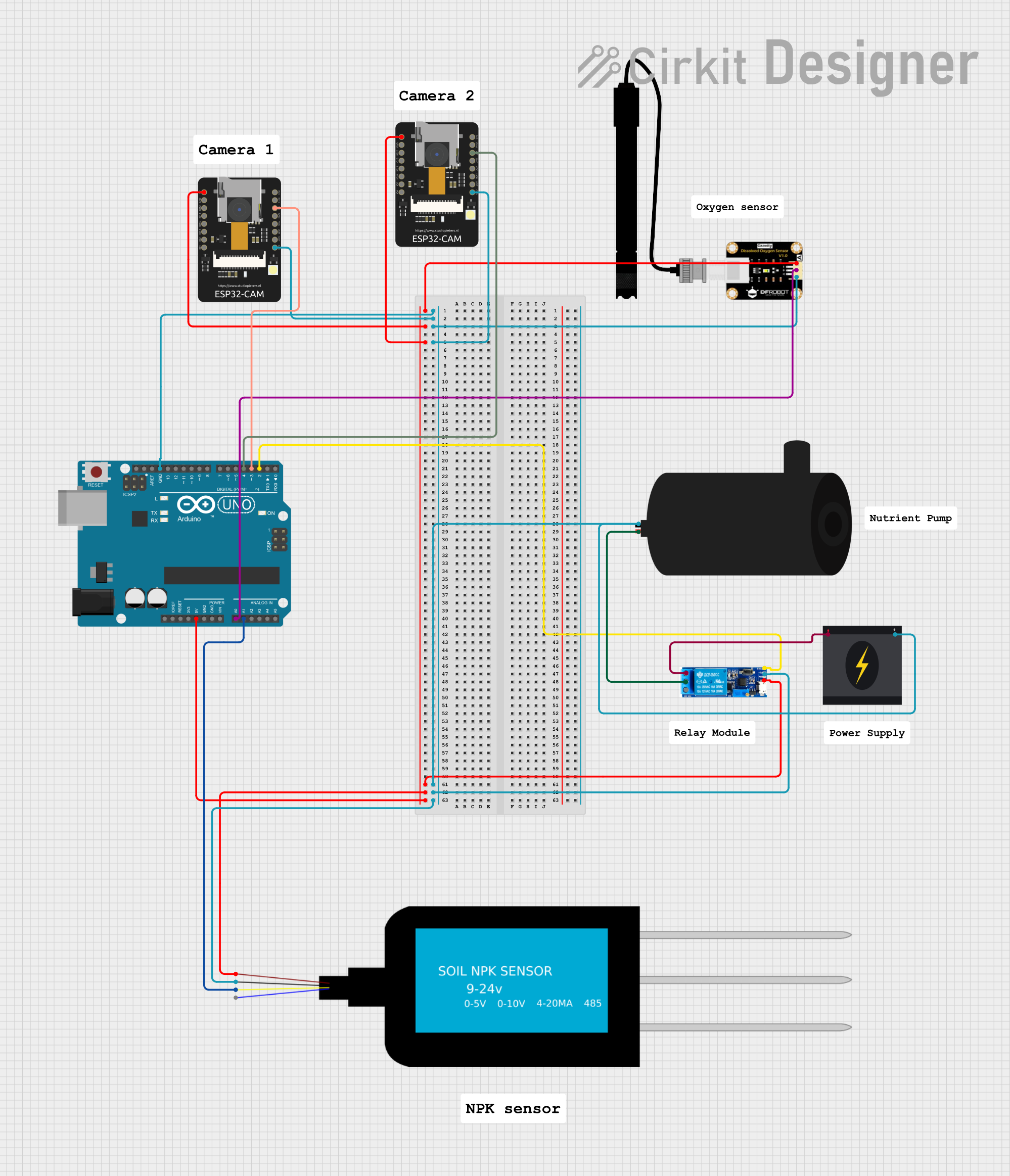
Circuit Documentation
Summary
This circuit is designed to monitor soil nutrient levels using an NPK Soil Sensor and control a water pump based on the sensor's readings. The system uses an Arduino UNO microcontroller to read the sensor data and activate a relay, which in turn controls the power to the water pump. The ESP32-CAM modules are included for potential camera functionality or wireless communication, although their specific roles are not defined in the provided code. The circuit is powered by a 5V supply that is distributed to the various components, and a 240V power source is used to power the water pump through the relay.
Component List
ESP32-CAM
- Description: A microcontroller module with Wi-Fi and camera capabilities.
- Pins: 5V, GND, IO12, IO13, IO15, IO14, IO2, IO4, VOT, VOR, VCC, IO0, IO16, 3V3
Do Sensor (Dissolved Oxygen Sensor)
- Description: A sensor used to measure the dissolved oxygen in a liquid.
- Pins: Vcc, Gnd, Out
Water Pump
- Description: An electromechanical device used to move water.
- Pins: Positive, Negative
Arduino UNO
- Description: A microcontroller board based on the ATmega328P.
- Pins: UNUSED, IOREF, Reset, 3.3V, 5V, GND, Vin, A0-A5, SCL, SDA, AREF, D0-D13
Relay Module 5V-30V
- Description: An electrically operated switch that allows you to control a high power circuit with a low power signal.
- Pins: Common Contact, Normally Open, Normally Closed, Trigger, V-, V+
240V Power Source
- Description: A high voltage power source used to power the water pump.
- Pins: Live, Neutral
NPK Soil Sensor
- Description: A sensor used to measure the Nitrogen, Phosphorus, and Potassium content in the soil.
- Pins: VCC, GND, A, B
Wiring Details
ESP32-CAM
- 5V: Connected to the 5V power net.
- GND: Connected to the ground net.
- IO0: Connected to digital pins on the Arduino UNO (D3 or D4).
Do Sensor (Dissolved Oxygen Sensor)
- Vcc: Connected to the 5V power net.
- Gnd: Connected to the ground net.
- Out: Connected to the A0 pin on the Arduino UNO.
Water Pump
- Positive: Connected to the common contact of the relay module.
- Negative: Connected to the ground net.
Arduino UNO
- 5V: Connected to the 5V power net.
- GND: Connected to the ground net.
- A0: Connected to the Do Sensor output.
- A1: Connected to the NPK Soil Sensor output.
- D2: Connected to the relay module trigger.
- D3, D4: Connected to the IO0 pin of the ESP32-CAM modules.
Relay Module 5V-30V
- V+: Connected to the 5V power net.
- V-: Connected to the ground net.
- Common Contact: Connected to the water pump positive.
- Normally Open: Connected to the 240V power source live.
- Trigger: Connected to the D2 pin on the Arduino UNO.
240V Power Source
- Live: Connected to the normally open contact of the relay module.
- Neutral: Connected to the ground net.
NPK Soil Sensor
- VCC: Connected to the 5V power net.
- GND: Connected to the ground net.
- A: Connected to the A1 pin on the Arduino UNO.
Documented Code
// Pin definitions
const int npkSensorPin = A1; // NPK Soil Sensor output connected to A1
const int relayPin = 2; // Relay trigger connected to D2

// Threshold for low nutrient level
const int nutrientThreshold = 400; // Adjust this value based on your sensor's calibration

void setup() {
  // Initialize serial communication
  Serial.begin(9600);

  // Set relay pin as output
  pinMode(relayPin, OUTPUT);
  digitalWrite(relayPin, LOW); // Ensure the relay is off initially

  // Initialize sensor pin
  pinMode(npkSensorPin, INPUT);
}

void loop() {
  // Read sensor value
  int npkSensorValue = analogRead(npkSensorPin);

  // Print sensor value to the serial monitor
  Serial.print("NPK Sensor Value: ");
  Serial.println(npkSensorValue);

  // Check if the nutrient level is below the threshold
  if (npkSensorValue < nutrientThreshold) {
    // Activate the water pump
    digitalWrite(relayPin, HIGH);
    Serial.println("Low nutrient detected! Pump activated.");
  } else {
    // Deactivate the water pump
    digitalWrite(relayPin, LOW);
    Serial.println("Nutrient level is normal. Pump deactivated.");
  }

  // Wait for 2 minutes before the next loop
  delay(120000); // 120,000 milliseconds = 2 minutes
}
This code is designed to run on the Arduino UNO microcontroller. It reads the value from the NPK Soil Sensor connected to analog pin A1 and compares it to a predefined threshold. If the nutrient level is below the threshold, it activates a relay which powers the water pump. The relay is controlled via digital pin D2. The system pauses for two minutes between readings.