Cirkit Designer
Your all-in-one circuit design IDE
Home /
Project Documentation
ESP32 and WS2812 RGB LED Strip Wi-Fi Controlled Smart Lighting System
Circuit Documentation
Summary
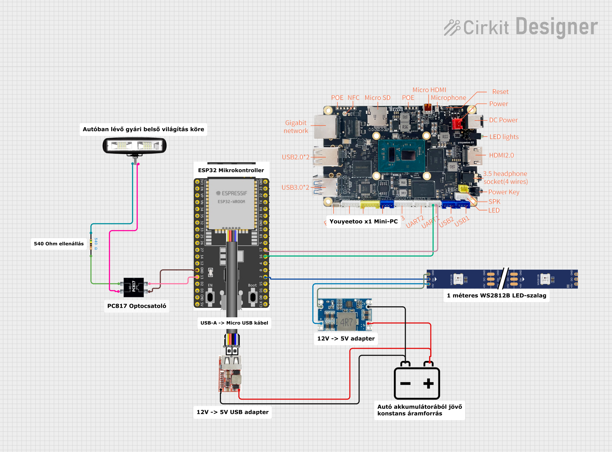
This document provides a detailed overview of a circuit that includes an ESP32 microcontroller, a WS2812 RGB LED strip, a step-down voltage regulator, a 12V battery, a USB regulator, a front light, a PC817 optocoupler, a Youyeetoo X1 module, and a resistor. The circuit is designed to control the RGB LED strip and the front light using the ESP32 microcontroller, with power supplied by a 12V battery and regulated to 5V using the step-down voltage regulator.
Component List
WS2812 RGB LED Strip
- Description: RGB LED strip with individually addressable LEDs.
- Pins: DIN, 5V, GND, DO
Mini 560 Step Down 20-7V to 5V
- Description: Step-down voltage regulator to convert 20-7V input to 5V output.
- Pins: IN-, IN+, OUT-, OUT+
12V Battery
- Description: Power source for the circuit.
- Pins: -, +
USB Regulator
- Description: Regulates USB power.
- Pins: VIN+, VIN-, 5V_USB_VO
Front Light
- Description: Light for the front of the device.
- Pins: POSITIF, NEGATIF
ESP32 Wroom Dev Kit
- Description: Microcontroller for controlling the circuit.
- Pins: 3V3, EN, VP, VN, GPIO 34, GPIO 35, GPIO 32, GPIO 33, GPIO 25, GPIO 26, GPIO 27, GPIO 14, GND, GPIO 13, SD2, SD3, CMD, V5, GPIO 23, GPIO 22, TXD, RXD, GPIO 21, GPIO 19, GPIO 18, GPIO 5, GPIO 17, GPIO 16, GPIO 4, GPIO 0, GPIO 2, GPIO 15, SD1, SD0, CLK
PC817
- Description: Optocoupler for isolating different sections of the circuit.
- Pins: Anode, Cathode, Collector, Emitter
Youyeetoo X1
- Description: Communication module.
- Pins: TXD, RXD
Resistor
- Description: Resistor with a resistance of 540 Ohms.
- Pins: pin1, pin2
Wiring Details
WS2812 RGB LED Strip
- DIN connected to GPIO 2 of ESP32 Wroom Dev Kit
- 5V connected to OUT+ of Mini 560 Step Down 20-7V to 5V
- GND connected to OUT- of Mini 560 Step Down 20-7V to 5V
Mini 560 Step Down 20-7V to 5V
- IN- connected to - of 12V Battery and VIN- of USB Regulator
- IN+ connected to + of 12V Battery and VIN+ of USB Regulator
- OUT- connected to GND of WS2812 RGB LED Strip
- OUT+ connected to 5V of WS2812 RGB LED Strip
12V Battery
- - connected to IN- of Mini 560 Step Down 20-7V to 5V and VIN- of USB Regulator
- + connected to IN+ of Mini 560 Step Down 20-7V to 5V and VIN+ of USB Regulator
USB Regulator
- VIN- connected to - of 12V Battery and IN- of Mini 560 Step Down 20-7V to 5V
- VIN+ connected to + of 12V Battery and IN+ of Mini 560 Step Down 20-7V to 5V
Front Light
- POSITIF connected to pin1 of Resistor
- NEGATIF connected to Cathode of PC817
ESP32 Wroom Dev Kit
- GND connected to Emitter of PC817
- GPIO 13 connected to Collector of PC817
- GPIO 2 connected to DIN of WS2812 RGB LED Strip
- GPIO 16 connected to TXD of Youyeetoo X1
- GPIO 17 connected to RXD of Youyeetoo X1
PC817
- Anode connected to pin2 of Resistor
- Cathode connected to NEGATIF of Front Light
- Collector connected to GPIO 13 of ESP32 Wroom Dev Kit
- Emitter connected to GND of ESP32 Wroom Dev Kit
Youyeetoo X1
- TXD connected to GPIO 16 of ESP32 Wroom Dev Kit
- RXD connected to GPIO 17 of ESP32 Wroom Dev Kit
Resistor
- pin1 connected to POSITIF of Front Light
- pin2 connected to Anode of PC817
Documented Code
ESP32 Wroom Dev Kit Code
sketch.ino
void setup() {
  // put your setup code here, to run once:

}

void loop() {
  // put your main code here, to run repeatedly:

}
documentation.txt