
Battery-Powered Heart Rate and SpO2 Monitor with OLED Display using MAX30102 and Arduino Nano
View and Edit Project In Cirkit Designer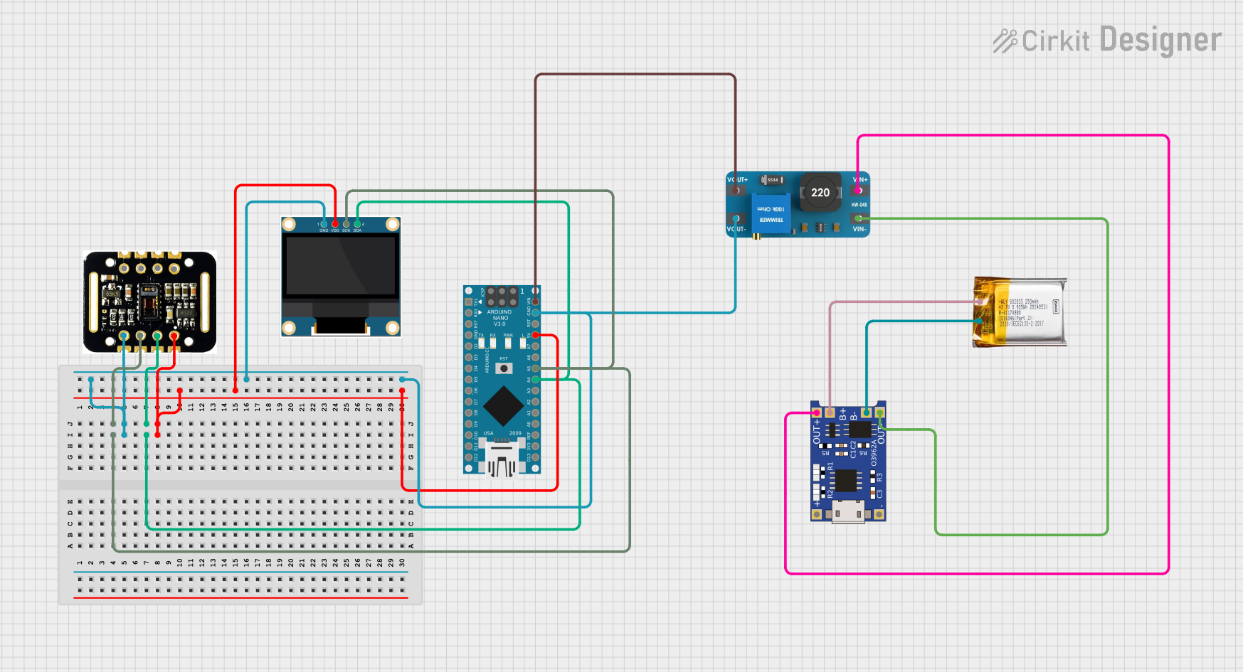
Circuit Documentation
Summary
This circuit interfaces a MAX30102 HR + SpO2 sensor and a 0.96" OLED display with an Arduino Nano. The sensor data is read via I2C and displayed on the OLED screen. The circuit is powered by a 3.7V LiPo battery, which is managed by a TP4056 charging module and a boost converter (MT3608) to provide a stable 5V supply.
Component List
MAX30102 HR + SpO2 sensor
- Description: A sensor module used for measuring heart rate and blood oxygen levels.
- Pins: INT, IRD, RD, GND, SCL, SDA, VIN
Arduino Nano
- Description: A small, complete, and breadboard-friendly board based on the ATmega328P.
- Pins: D1/TX, D0/RX, RESET, GND, D2, D3, D4, D5, D6, D7, D8, D9, D10, D11/MOSI, D12/MISO, VIN, 5V, A7, A6, A5, A4, A3, A2, A1, A0, AREF, 3V3, D13/SCK
0.96" OLED
- Description: A small OLED display module used for displaying text and graphics.
- Pins: GND, VDD, SCK, SDA
3.7V LiPo Battery
- Description: A rechargeable lithium polymer battery.
- Pins: +Ve, GND
TP4056
- Description: A lithium battery charger module with overcharge protection.
- Pins: OUT-, B-, B+, OUT+, IN-, IN+
Boost Converter (MT3608)
- Description: A DC-DC step-up converter used to boost the voltage from the LiPo battery to 5V.
- Pins: OUTPUT +, OUTPUT -, INPUT +, INPUT -
Wiring Details
MAX30102 HR + SpO2 sensor
- SCL connected to Arduino Nano A5 and 0.96" OLED SCK
- GND connected to 0.96" OLED GND, Arduino Nano GND, and Boost Converter OUTPUT -
- SDA connected to Arduino Nano A4 and 0.96" OLED SDA
- VIN connected to 0.96" OLED VDD and Arduino Nano 5V
Arduino Nano
- A5 connected to MAX30102 HR + SpO2 sensor SCL and 0.96" OLED SCK
- GND connected to MAX30102 HR + SpO2 sensor GND, 0.96" OLED GND, and Boost Converter OUTPUT -
- A4 connected to MAX30102 HR + SpO2 sensor SDA and 0.96" OLED SDA
- 5V connected to MAX30102 HR + SpO2 sensor VIN and 0.96" OLED VDD
- VIN connected to Boost Converter OUTPUT +
0.96" OLED
- SCK connected to MAX30102 HR + SpO2 sensor SCL and Arduino Nano A5
- GND connected to MAX30102 HR + SpO2 sensor GND, Arduino Nano GND, and Boost Converter OUTPUT -
- SDA connected to MAX30102 HR + SpO2 sensor SDA and Arduino Nano A4
- VDD connected to MAX30102 HR + SpO2 sensor VIN and Arduino Nano 5V
3.7V LiPo Battery
- +Ve connected to TP4056 B+
- GND connected to TP4056 B-
TP4056
- B+ connected to 3.7V LiPo Battery +Ve
- B- connected to 3.7V LiPo Battery GND
- OUT- connected to Boost Converter INPUT -
- OUT+ connected to Boost Converter INPUT +
Boost Converter (MT3608)
- OUTPUT + connected to Arduino Nano VIN
- OUTPUT - connected to MAX30102 HR + SpO2 sensor GND, 0.96" OLED GND, and Arduino Nano GND
- INPUT + connected to TP4056 OUT+
- INPUT - connected to TP4056 OUT-
Code Documentation
/*
 * This Arduino Sketch interfaces with a MAX30102 HR + SpO2 sensor and a 0.96" OLED
 * display using an Arduino Nano. The sensor data is read via I2C and displayed
 * on the OLED screen.
 */

#include <Wire.h>
#include <Adafruit_GFX.h>
#include <Adafruit_SSD1306.h>
#include "MAX30105.h"

#define SCREEN_WIDTH 128
#define SCREEN_HEIGHT 64
#define OLED_RESET    -1
Adafruit_SSD1306 display(SCREEN_WIDTH, SCREEN_HEIGHT, &Wire, OLED_RESET);

MAX30105 particleSensor;

void setup() {
  Wire.begin();
  Serial.begin(115200);

  if (!display.begin(SSD1306_I2C_ADDRESS, OLED_RESET)) {
    Serial.println(F("SSD1306 allocation failed"));
    for (;;);
  }
  display.display();
  delay(2000);
  display.clearDisplay();

  if (!particleSensor.begin(Wire, I2C_SPEED_FAST)) {
    Serial.println(F("MAX30105 was not found. Please check wiring/power."));
    for (;;);
  }
  particleSensor.setup();
}

void loop() {
  long irValue = particleSensor.getIR();
  long redValue = particleSensor.getRed();

  display.clearDisplay();
  display.setTextSize(1);
  display.setTextColor(SSD1306_WHITE);
  display.setCursor(0, 0);
  display.print(F("IR: "));
  display.println(irValue);
  display.print(F("RED: "));
  display.println(redValue);
  display.display();

  delay(1000);
}
This code initializes the I2C communication, sets up the OLED display, and configures the MAX30102 sensor. In the main loop, it reads the IR and Red values from the sensor and displays them on the OLED screen.