
Arduino Mega 2560-Based Smart Hydroponic System with Wi-Fi Control
View and Edit Project In Cirkit Designer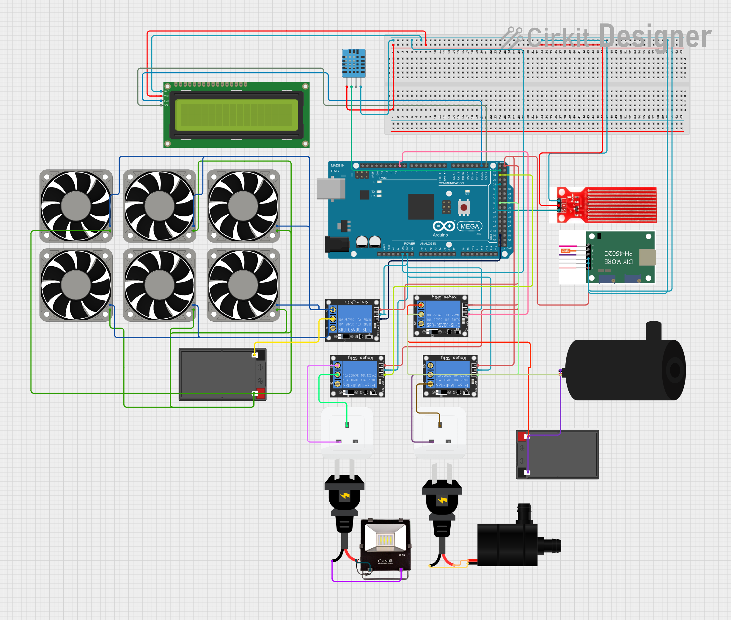
Circuit Documentation
Summary
This circuit is designed to monitor and control various environmental parameters such as temperature, humidity, pH levels, and water levels. It uses an Arduino Mega 2560 microcontroller to interface with sensors and control relays for actuating devices like water pumps, fans, and floodlights. The system also includes an LCD display for real-time data visualization and a Bluetooth module for wireless communication.
Component List
Water Sensor
- Pins: Signal, VCC, GND
- Description: Detects the presence of water.
40 Fan 12v
- Pins: +12V, -12V
- Description: Provides cooling by circulating air.
1-Channel Relay (5V 10A)
- Pins: NC, signal, C, power, NO, ground
- Description: Controls high-power devices using a low-power signal.
Flood Lights 12v
- Pins: 12V, GROUND
- Description: Provides illumination.
Arduino Mega 2560
- Pins: IOREF, RESET, 3V3, 5V, GND, VIN, A0-A15, D0-D53, AREF, SDA, SCL
- Description: Microcontroller for interfacing with sensors and actuators.
DHT11 Humidity and Temperature Sensor
- Pins: VDD, DATA, NULL, GND
- Description: Measures humidity and temperature.
Water Pump
- Pins: VCC, GND
- Description: Pumps water.
12v 7ah Battery
- Pins: 12v +, 12v -
- Description: Provides power to the circuit.
16x2 I2C LCD
- Pins: GND, VCC, SDA, SCL
- Description: Displays data.
Socket
- Pins: earth, life, neutral
- Description: Provides AC power.
AC Source
- Pins: +, -
- Description: Provides AC power.
Water Pump
- Pins: positive, negative
- Description: Pumps water.
ph4502c
- Pins: VCC, G1, G2, Po, Do, To
- Description: Measures pH levels.
Wiring Details
Water Sensor
- Signal connected to Arduino Mega 2560 pin D28
- VCC connected to DHT11 Humidity and Temperature Sensor VDD and 16x2 I2C LCD VCC
- GND connected to Arduino Mega 2560 GND, 16x2 I2C LCD GND, and ph4502c G1 and G2
40 Fan 12v
- +12V connected to 12v 7ah Battery 12v +
- -12V connected to 1-Channel Relay (5V 10A) NO and 12v 7ah Battery 12v -
1-Channel Relay (5V 10A)
- NC connected to socket earth
- signal connected to Arduino Mega 2560 pins D9 PWM, D50, D36, and D24
- C connected to socket life, water pump positive, and 12v 7ah Battery 12v -
- power connected to Arduino Mega 2560 GND
- NO connected to battery +
Flood Lights 12v
- 12V connected to AC source +
- GROUND connected to AC source -
Arduino Mega 2560
- GND connected to DHT11 Humidity and Temperature Sensor GND, 16x2 I2C LCD GND, Water sensor GND, and ph4502c G1 and G2
- D21/SCL connected to 16x2 I2C LCD SCL
- D20/SDA connected to 16x2 I2C LCD SDA
- D9 PWM connected to 1-Channel Relay (5V 10A) signal
- D50 connected to 1-Channel Relay (5V 10A) signal
- D36 connected to 1-Channel Relay (5V 10A) signal
- D28 connected to Water sensor Signal
- D24 connected to 1-Channel Relay (5V 10A) signal
- D22 connected to DHT11 Humidity and Temperature Sensor DATA
- 5V connected to 1-Channel Relay (5V 10A) ground and ph4502c VCC
DHT11 Humidity and Temperature Sensor
- VDD connected to 16x2 I2C LCD VCC and Water sensor VCC
- DATA connected to Arduino Mega 2560 pin D22
- GND connected to Arduino Mega 2560 GND
Water Pump
- VCC connected to AC source +
- GND connected to AC source -
12v 7ah Battery
- 12v + connected to 40 Fan 12v +12V
- 12v - connected to 1-Channel Relay (5V 10A) C
16x2 I2C LCD
- GND connected to Arduino Mega 2560 GND
- VCC connected to DHT11 Humidity and Temperature Sensor VDD and Water sensor VCC
- SDA connected to Arduino Mega 2560 pin D20/SDA
- SCL connected to Arduino Mega 2560 pin D21/SCL
Socket
- earth connected to 1-Channel Relay (5V 10A) NC
- life connected to 1-Channel Relay (5V 10A) C
AC Source
- + connected to Water Pump VCC and Flood Lights 12v 12V
- - connected to Water Pump GND and Flood Lights 12v GROUND
Water Pump
- positive connected to 1-Channel Relay (5V 10A) C
- negative connected to battery -
ph4502c
- VCC connected to Arduino Mega 2560 5V
- G1 connected to Arduino Mega 2560 GND
- G2 connected to Arduino Mega 2560 GND
Documented Code
#include <CRC_AudioManager.h>
#include <CRC_DistanceSensor.h>
#include <CRC_Hardware.h>
#include <CRC_IR_AnalogDistance.h>
#include <CRC_IR_BinaryDistance.h>
#include <CRC_Lights.h>
#include <CRC_Motor.h>
#include <CRC_PCA9635.h>
#include <CRC_PingDistance.h>
#include <CRC_Sensors.h>
#include <CRC_Simulation.h>
#include <DHT.h>  // Para el sensor de humedad y temperatura
#include <ESP8266WiFi.h>  // Módulo Wi-Fi
#include <SoftwareSerial.h>  // Comunicación Bluetooth
#include <LiquidCrystal_I2C.h>  // Librería para LCD I2C

// Definimos los pines de los sensores y relés
#define DHTPIN 2  // Pin del sensor DHT22
#define DHTTYPE DHT22  // Tipo de sensor DHT
#define PH_PIN A0  // Pin para leer el sensor de pH
#define WATER_LEVEL_PIN 3  // Pin del sensor de nivel de agua

// Pines de los relés para controlar las bombas y coolers
#define RELAY_WATER_PUMP 7  // Relé de la bomba de agua
#define RELAY_ACID_PUMP 8  // Relé de la bomba de ácido
#define RELAY_SUBSTRATE_1 9  // Relé de la bomba de sustrato 1
#define RELAY_SUBSTRATE_2 10  // Relé de la bomba de sustrato 2
#define RELAY_COOLERS 11  // Relé de los coolers

// Definimos el sensor DHT
DHT dht(DHTPIN, DHTTYPE);

// Configuramos el módulo Bluetooth en pines 10 y 11
SoftwareSerial BTSerial(10, 11);  // RX, TX para Bluetooth

// Inicializamos la pantalla LCD con dirección I2C
LiquidCrystal_I2C lcd(0x27, 16, 2);  // Dirección y tamaño de la LCD (ajusta según tu pantalla)

// Variables para los sensores
float temperatura;
float humedad;
float ph;
int nivelAgua;

// Umbrales de control
const float PH_MAX = 7.0;  // Si el pH supera este valor, se añade ácido
const float PH_MIN = 5.5;  // Si el pH baja de este valor, se considera agua mala
const float TEMPERATURE_THRESHOLD = 20.0;  // Umbral de temperatura para activar los coolers

// Temporizador de la bomba de agua
unsigned long tiempoEncendido = 5000;  // Bomba encendida por