Arduino-Controlled DC Motor with Pushbutton Activation and LED Indicator
Circuit Documentation
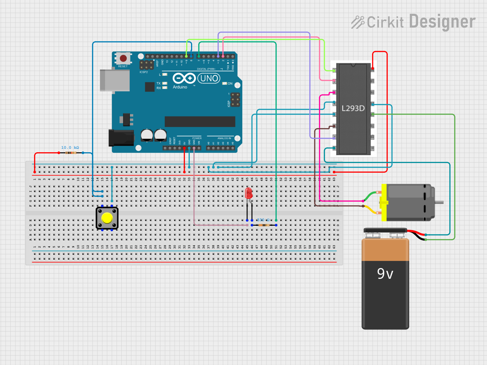
Summary of the Circuit
This circuit appears to be designed to control a DC motor using an Arduino UNO and an L293D motor driver. The circuit includes a pushbutton to trigger an input, a 10k Ohm resistor for pull-up or pull-down configuration, a red LED with a 330 Ohm current-limiting resistor, and a 9V battery to power the motor through the L293D. The Arduino UNO is used as the central control unit, interfacing with the pushbutton, LED, and motor driver to control the motor's operation.
Component List
Arduino UNO
- Microcontroller board based on the ATmega328P
- It has 14 digital input/output pins, 6 analog inputs, a 16 MHz quartz crystal, a USB connection, a power jack, an ICSP header, and a reset button.
Pushbutton
- A simple switch mechanism for controlling some aspect of a machine or a process.
Resistor (10k Ohm)
- A passive two-terminal electrical component that implements electrical resistance as a circuit element.
LED: Two Pin (red)
- A red light-emitting diode that emits light when a current flows through it.
Resistor (330 Ohm)
- A passive two-terminal electrical component used to limit current to the LED.
DC Motor
- An electric motor that runs on direct current (DC) electricity.
L293D Motor Driver
- A dual H-bridge motor driver integrated circuit (IC) that allows the motor to be driven in both directions.
9V Battery
- A standard 9V battery used to provide power to the motor.
Wiring Details
Arduino UNO
- 5V connected to the 10k Ohm resistor and L293D Vcc1.
- GND connected to the pushbutton, L293D GND, and LED cathode.
- D8 connected to the pushbutton through the 10k Ohm resistor.
- D7 connected to the LED anode through the 330 Ohm resistor.
- D9 connected to L293D Enable 1,2.
- D3 connected to L293D Input 2.
- D2 connected to L293D Input 1.
Pushbutton
- One side connected to Arduino D8 through the 10k Ohm resistor.
- The other side connected to Arduino GND.
Resistor (10k Ohm)
- One end connected to Arduino 5V.
- The other end connected to the pushbutton and Arduino D8.
LED: Two Pin (red)
- Anode connected to Arduino D7 through the 330 Ohm resistor.
- Cathode connected to Arduino GND.
Resistor (330 Ohm)
- One end connected to Arduino D7.
- The other end connected to the LED anode.
DC Motor
- One pin connected to L293D Output 1.
- The other pin connected to L293D Output 2.
L293D Motor Driver
- Enable 1,2 connected to Arduino D9.
- Input 1 connected to Arduino D2.
- Input 2 connected to Arduino D3.
- Output 1 and Output 2 connected to the DC Motor.
- Vcc1 connected to Arduino 5V.
- Vcc2 connected to the 9V Battery positive terminal.
- GND connected to Arduino GND and 9V Battery negative terminal.
9V Battery
- Positive terminal connected to L293D Vcc2.
- Negative terminal connected to L293D GND.
Documented Code
Arduino UNO Code (sketch.ino)
void setup() {
  // put your setup code here, to run once:

}

void loop() {
  // put your main code here, to run repeatedly:

}
The provided code is a template with empty setup() and loop() functions. The setup() function is intended for code that runs once upon reset or power-up, while the loop() function contains code that runs continuously. To control the motor, code for initializing the motor driver pins and logic for controlling the motor direction and speed should be added to these functions.