
Arduino GSM Security System with Motion Detection and Light Sensing
View and Edit Project In Cirkit Designer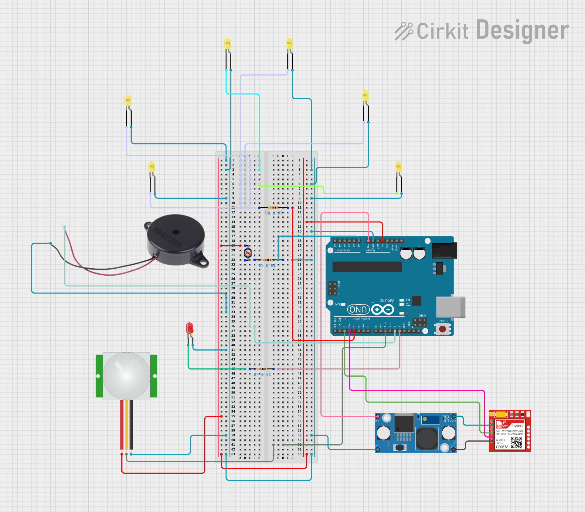
Circuit Documentation
Summary
This document provides a detailed overview of a circuit designed to interface an Arduino UNO with various components including LEDs, a SIM800L GSM module, a PIR sensor, an LDR (photocell), a buzzer, and an LM2596 step-down module. The circuit is designed to perform tasks that likely involve sensing, actuation, and communication via the GSM network.
Component List
Microcontroller
- Arduino UNO: A microcontroller board based on the ATmega328P. It has a variety of digital and analog I/O pins and is used as the central controller for the circuit.
Communication Module
- Sim800l: A GSM/GPRS module that allows the circuit to communicate over mobile network for tasks such as sending SMS or enabling internet connectivity.
Sensors
- PIR sensor: A motion sensor that detects the presence of humans or animals by sensing changes in infrared levels.
- Photocell (LDR): A light-dependent resistor that changes resistance based on the ambient light level.
Actuators
- Buzzer: An electronic component that produces sound. It can be used for audible alerts or alarms.
Power Management
- LM2596 Step Down Module: A voltage regulator that steps down the input voltage to a lower, regulated output voltage.
Passive Components
- Resistor: A component that provides resistance in the circuit, used for current limiting or voltage division. In this circuit, 10kΩ resistors are used.
- LED: Two Pin (yellow): Yellow light-emitting diodes used as visual indicators.
- LED: Two Pin (red): A red light-emitting diode used as a visual indicator.
Wiring Details
Arduino UNO
- Digital Pin 4 (D4) connected to a 10kΩ resistor.
- Digital Pin 10 (D10) connected to the PIR sensor signal pin.
- Digital Pin 12 (D12) connected to the buzzer positive pin.
- Digital Pin 13 (D13) connected to a 10kΩ resistor leading to a red LED.
- Analog Pin 0 (A0) connected to a 10kΩ resistor in series with an LDR.
- 5V pin connected to the VDD pin of the PIR sensor and one leg of the LDR.
- GND pin connected to the common ground of the circuit.
- Vin pin connected to the IN+ pin of the LM2596 Step Down Module.
- Digital Pin 2 (D2) connected to the RXD pin of the Sim800l.
- Digital Pin 3 (D3) connected to the TXD pin of the Sim800l.
Sim800l
- VCC connected to the OUT+ of the LM2596 Step Down Module.
- GND connected to the OUT- of the LM2596 Step Down Module.
LEDs (Yellow)
- Anodes of all yellow LEDs connected to the common ground of the circuit.
- Cathodes of four yellow LEDs connected to a 10kΩ resistor, which is connected to Digital Pin 4 (D4) of the Arduino UNO.
LED (Red)
- Anode connected to the common ground of the circuit.
- Cathode connected to a 10kΩ resistor, which is connected to Digital Pin 13 (D13) of the Arduino UNO.
Buzzer
- Negative pin connected to the common ground of the circuit.
- Positive pin connected to Digital Pin 12 (D12) of the Arduino UNO.
PIR Sensor
- VDD connected to the 5V pin of the Arduino UNO.
- GND connected to the common ground of the circuit.
- SIG connected to Digital Pin 10 (D10) of the Arduino UNO.
Photocell (LDR)
- One leg connected to the 5V pin of the Arduino UNO.
- The other leg connected to a 10kΩ resistor, which is connected to Analog Pin 0 (A0) of the Arduino UNO.
LM2596 Step Down Module
- IN+ connected to the Vin pin of the Arduino UNO.
- OUT+ connected to the VCC pin of the Sim800l.
- OUT- connected to the GND pin of the Sim800l.
Documented Code
Arduino UNO Code (sketch.ino)
void setup() {
  // put your setup code here, to run once:

}

void loop() {
  // put your main code here, to run repeatedly:

}
Note: The provided code is a template and does not contain any functional code. It needs to be populated with the logic to control the circuit based on the requirements.