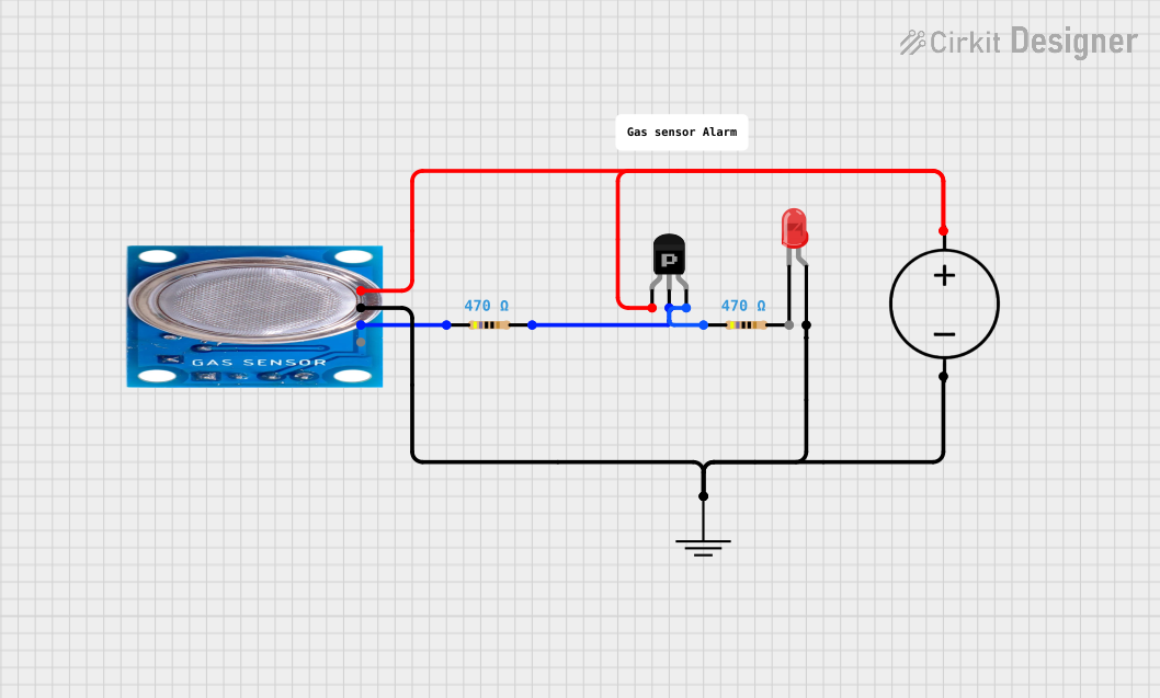
MQ-5 Gas Sensor Circuit with PNP Transistor and LED Indicator

Circuit Documentation
Summary of the Circuit
This circuit appears to be a simple sensor interface with a power supply, a gas sensor (MQ-5), a PNP transistor acting as a switch, and two resistors. The circuit is designed to detect the presence of certain gases and likely to activate an LED when the gas concentration reaches a certain threshold. The MQ-5 sensor has both digital and analog outputs, but in this circuit, only the digital output is used. The LED is connected to the ground through the anode, which is unconventional and suggests that the LED is controlled by the PNP transistor.
Component List
Ground (GND)
- Description: Common ground reference point for the circuit.
MQ-5 Gas Sensor
- Description: A gas sensor for detecting LPG, natural gas, and coal gas.
- Pins:
- VCC: Power supply input.
- GND: Ground connection.
- Digi Out: Digital output signal.
- Analog out: Analog output signal (not used in this circuit).
Resistors (2x)
- Description: Passive components used to limit current or divide voltages.
- Resistance: 470 Ohms each.
LED: Two Pin (red)
- Description: A red light-emitting diode used as an indicator.
- Pins:
- Cathode: Negative terminal.
- Anode: Positive terminal.
PNP Transistor (CBE)
- Description: A type of bipolar junction transistor used as a switch or amplifier.
- Pins:
- Collector: Connected to the load (LED).
- Base: Controls the transistor switching.
- Emitter: Emitter terminal.
DC Power Source
- Description: Provides the necessary power to the circuit.
- Pins:
- Ground: Ground terminal.
- Positive: Positive voltage supply.
Comment
- Description: A placeholder for additional notes or comments (not a physical component).
Wiring Details
Ground (GND)
- Connected to:
- Ground pin of the DC Power Source.
- GND pin of the MQ-5 Gas Sensor.
- Anode pin of the LED (Note: This is unconventional and suggests that the LED is controlled by the PNP transistor).
MQ-5 Gas Sensor
- VCC pin connected to the Positive pin of the DC Power Source.
- GND pin connected to the Ground (GND).
- Digi Out pin connected to one end of a 470 Ohm Resistor.
Resistors
- One 470 Ohm Resistor connected between the Digi Out pin of the MQ-5 Gas Sensor and the Base pin of the PNP Transistor.
- Another 470 Ohm Resistor connected between the Emitter pin of the PNP Transistor and the Positive pin of the DC Power Source.
LED: Two Pin (red)
- Cathode pin not connected (floating).
- Anode pin connected to the Ground (GND).
PNP Transistor (CBE)
- Collector pin connected to the Positive pin of the DC Power Source.
- Base pin connected to one end of a 470 Ohm Resistor (the other end connected to the Digi Out pin of the MQ-5 Gas Sensor).
- Emitter pin connected to one end of a 470 Ohm Resistor (the other end connected to the Positive pin of the DC Power Source).
DC Power Source
- Ground pin connected to the Ground (GND).
- Positive pin connected to:
- VCC pin of the MQ-5 Gas Sensor.
- Collector pin of the PNP Transistor.
- One end of a 470 Ohm Resistor (the other end connected to the Emitter pin of the PNP Transistor).
Documented Code
No code has been provided for any microcontrollers in the circuit. If the circuit is intended to be controlled or monitored by a microcontroller, the code would be necessary to manage the digital output of the MQ-5 sensor and to control the LED through the PNP transistor. Without the code, the behavior of the circuit cannot be fully documented.