Bluno Beetle-Based Motion Detection System with Visual Feedback
Circuit Documentation
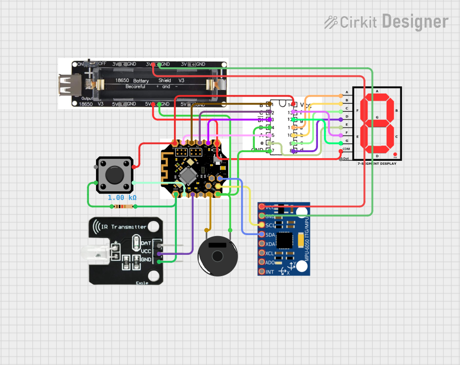
Summary
This circuit integrates various components to perform a set of functions that likely include motion sensing, user input, visual output through a 7-segment display, and audio signaling. The central processing unit is the "bluno beetle" microcontroller, which interfaces with an MPU-6050 motion sensor, a tactile switch, a piezo buzzer, a BCD-to-Seven-Segment Decoder, an IR transmitter, a 7-segment display, and a resistor. Power is supplied by a 1-Way 18650 Battery Holder. The circuit is designed to be compact and efficient, suitable for applications requiring user interaction, motion detection, and visual and auditory feedback.
Component List
Bluno Beetle
- Description: A small Arduino-compatible microcontroller with Bluetooth 4.0 capability.
- Pins: 5V, A0-A3, VIN, GND, D2-D5, RX, TX, SDA, SCL
MPU-6050
- Description: A motion processing unit that contains a 3-axis gyroscope and a 3-axis accelerometer.
- Pins: VCC, GND, SCL, SDA, XDA, XCL, AD0, INT
Tactile Switch Buttons - 12mm Square
- Description: A simple switch that provides a digital input when pressed.
- Pins: 1, 2, 3, 4
Piezo Buzzer
- Description: An electronic device that emits sound when an electrical signal is applied.
- Pins: pin 1, pin 2
BCD-to-Seven-Segment Decoders
- Description: A decoder that converts binary-coded decimal input into control signals for a 7-segment display.
- Pins: GND, E, A, D, !BI, C, B, VCC, f, a, b, c, d
IR Transmitter
- Description: An infrared LED that can be used to transmit data or signals.
- Pins: DAT, VCC, GND
1-Way 18650 Battery Holder
- Description: A battery holder for a single 18650 lithium-ion cell.
- Pins: 3V, GND, 5V
7segment on
- Description: A 7-segment LED display that shows numerical digits.
- Pins: A, B, C, D, E, F, G, COM, dot
Resistor
- Description: A passive electrical component that provides resistance in a circuit.
- Pins: pin1, pin2
- Properties: 1000 Ohms resistance
Wiring Details
Bluno Beetle
- 5V connected to BCD-to-Seven-Segment Decoders VCC and Tactile Switch Button pin 1
- A0 connected to BCD-to-Seven-Segment Decoders A
- A1 connected to BCD-to-Seven-Segment Decoders B
- A2 connected to BCD-to-Seven-Segment Decoders C
- A3 connected to BCD-to-Seven-Segment Decoders !BI
- VIN connected to 1-Way 18650 Battery Holder 5V
- GND connected to 1-Way 18650 Battery Holder GND, Piezo Buzzer pin 1, BCD-to-Seven-Segment Decoders GND, and IR Transmitter GND
- D2 connected to Piezo Buzzer pin 2
- D3 not connected
- D4 connected to IR Transmitter VCC
- D5 connected to Tactile Switch Button pin 2
- RX not connected
- TX not connected
- SDA connected to MPU-6050 SDA
- SCL connected to MPU-6050 SCL
MPU-6050
- VCC connected to 1-Way 18650 Battery Holder 3V
- GND connected to 1-Way 18650 Battery Holder GND
- SCL connected to Bluno Beetle SCL
- SDA connected to Bluno Beetle SDA
Tactile Switch Buttons - 12mm Square
- Pin 1 connected to Bluno Beetle 5V
- Pin 2 connected to Bluno Beetle D5
- Pin 3 not connected
- Pin 4 connected to Resistor pin1
Piezo Buzzer
- Pin 1 connected to 1-Way 18650 Battery Holder GND
- Pin 2 connected to Bluno Beetle D2
BCD-to-Seven-Segment Decoders
- VCC connected to Bluno Beetle 5V
- GND connected to 1-Way 18650 Battery Holder GND
- A connected to Bluno Beetle A0
- B connected to Bluno Beetle A1
- C connected to Bluno Beetle A2
- D connected to 1-Way 18650 Battery Holder GND
- !BI connected to Bluno Beetle A3
- E connected to 7segment on E
- F connected to 7segment on F
- A, B, C, D, E, F, G connected to corresponding pins on 7segment on
IR Transmitter
- VCC connected to Bluno Beetle D4
- GND connected to Resistor pin2
1-Way 18650 Battery Holder
- 3V connected to MPU-6050 VCC
- GND connected to MPU-6050 GND, Bluno Beetle GND, Piezo Buzzer pin 1, BCD-to-Seven-Segment Decoders GND, and IR Transmitter GND
- 5V connected to Bluno Beetle VIN and 7segment on COM
7segment on
- COM connected to 1-Way 18650 Battery Holder 5V
- A, B, C, D, E, F, G connected to corresponding pins on BCD-to-Seven-Segment Decoders
Resistor
- Pin1 connected to Tactile Switch Button pin 4
- Pin2 connected to IR Transmitter GND
Documented Code
There is no code provided for the microcontroller in this circuit. The functionality of the circuit will depend on the embedded code that controls the microcontroller's interaction with the sensors, the display, and other components. The code would typically initialize the hardware interfaces (e.g., I2C for the MPU-6050), set up input/output pins, handle button presses, read sensor data, and update the display or transmit IR signals accordingly. Without the code, the specific behavior of the circuit cannot be documented.