
Raspberry Pi 5 RFID Access Control System with LCD Feedback and Dual Motor Control
View and Edit Project In Cirkit Designer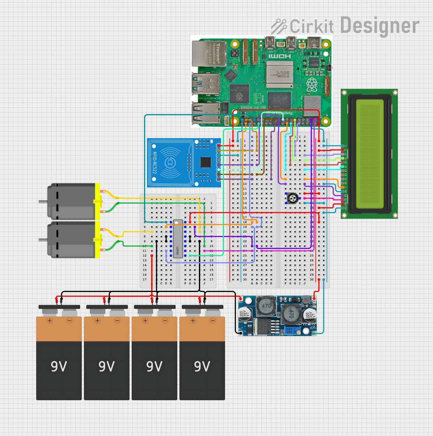
Circuit Documentation
Summary
This circuit integrates a Raspberry Pi 5 with an RFID-RC522 module, an LCD Display (16x2), a pair of DC Motors controlled by an L293D motor driver, a trimmer potentiometer, and an XL6009 voltage regulator. The circuit is powered by multiple 9V batteries. The Raspberry Pi 5 serves as the central processing unit, interfacing with the RFID module and the LCD display for user interaction, and controlling the DC motors via the L293D motor driver. The voltage regulator ensures that components receive the correct voltage, and the potentiometer is used for adjusting contrast on the LCD display.
Component List
Raspberry Pi 5
- A microcomputer with multiple GPIO pins used for interfacing with other components in the circuit.
RFID-RC522
- An RFID reader module for reading RFID tags, connected to the Raspberry Pi via SPI interface.
LCD Display 16x2
- A 16x2 character LCD display for showing information, interfaced with the Raspberry Pi through GPIO pins.
XL6009 Voltage Regulator
- A DC-DC voltage regulator that steps up the input voltage to a higher, regulated output voltage.
DC Motor
- Two DC motors controlled by the L293D motor driver, used for motion-related applications.
L293D
- A motor driver IC that provides bidirectional drive currents for motors with speed and direction control.
Trimmer Potentiometer
- A variable resistor used to adjust the contrast of the LCD display.
Battery 9V
- Four 9V batteries providing power to the circuit.
Wiring Details
Raspberry Pi 5
- GPIO 26 connected to RFID-RC522 RST
- GPIO 18, 27, 22, 23, 24, 25 connected to LCD Display DB7, DB6, DB5, DB4, E, RS respectively
- GPIO 9, 10, 11, 8 connected to RFID-RC522 MISO, MOSI, SCK, SDA respectively
- GPIO 20, 16, 3, 2 connected to L293D Input 1, Input 2, Input 4, Input 3 respectively
- GPIO 13, 12 connected to L293D Enable 1,2, Enable 3,4 respectively
- 5V connected to Trimmer Potentiometer leg1, LCD Display LEDA, VDD, and XL6009 Voltage Regulator OUT +
- 3.3v connected to RFID-RC522 3.3V
- GND connected to Trimmer Potentiometer leg2, LCD Display LEDK, RW, VSS, RFID-RC522 GND, and XL6009 Voltage Regulator OUT -
RFID-RC522
- SDA, SCK, MOSI, MISO, IRQ, GND, RST, 3.3V connected to Raspberry Pi as specified above.
LCD Display 16x2
- DB7, DB6, DB5, DB4, E, RS, LEDA, VDD connected to Raspberry Pi as specified above.
- VO connected to Trimmer Potentiometer wiper
- LEDK, RW, VSS connected to GND
XL6009 Voltage Regulator
- OUT +, OUT - connected to Raspberry Pi 5V and GND respectively
- IN +, IN - connected to the positive and negative terminals of the 9V batteries respectively
DC Motor
- Each motor has two pins connected to L293D Output 1, Output 2 for one motor, and Output 3, Output 4 for the other motor.
L293D
- Enable 1,2, Input 1, Output 1, Output 2, VCC2 connected to Raspberry Pi GPIO 13, GPIO 20, DC Motor pin 2, DC Motor pin 1, and 9V battery VCC respectively.
- Enable 3,4, Input 4, Output 4, Output 3, VCC1 connected to Raspberry Pi GPIO 12, GPIO 3, DC Motor pin 2, DC Motor pin 1, and Trimmer Potentiometer leg1 respectively.
- GND connected to the negative terminal of the 9V batteries.
Trimmer Potentiometer
- Leg1 connected to Raspberry Pi 5V
- Wiper connected to LCD Display VO
- Leg2 connected to GND
Battery 9V
- Each battery has VCC and GND connected to the circuit as specified above.
Documented Code
There is no code provided for the microcontrollers in the circuit. If code becomes available, it should be documented here with explanations for each function and routine, including setup and loop functions, interrupt service routines, and any custom functions used to control the hardware components.