
Arduino Nano-Based Pushbutton-Controlled LED System with I2C Communication
View and Edit Project In Cirkit Designer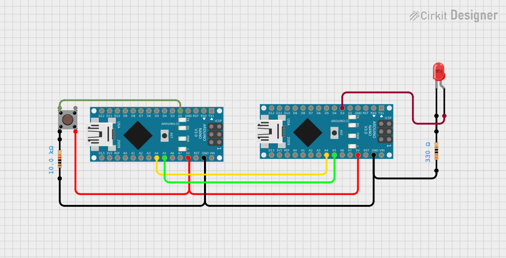
Circuit Documentation
Summary
This circuit involves two Arduino Nano microcontrollers, a pushbutton, two resistors, and a red LED. The circuit is designed to read the state of a pushbutton and transmit this state to another Arduino Nano, which then controls an LED based on the received state.
Component List
Arduino Nano
- Description: A small, complete, and breadboard-friendly board based on the ATmega328P.
- Pins: D1/TX, D0/RX, RESET, GND, D2, D3, D4, D5, D6, D7, D8, D9, D10, D11/MOSI, D12/MISO, VIN, 5V, A7, A6, A5, A4, A3, A2, A1, A0, AREF, 3V3, D13/SCK
Pushbutton
- Description: A simple pushbutton switch.
- Pins: Pin 3 (out), Pin 4 (out), Pin 1 (in), Pin 2 (in)
Resistor (10k Ohms)
- Description: A resistor with a resistance of 10k Ohms.
- Pins: pin1, pin2
LED: Two Pin (red)
- Description: A red LED with two pins.
- Pins: cathode, anode
Resistor (330 Ohms)
- Description: A resistor with a resistance of 330 Ohms.
- Pins: pin1, pin2
Wiring Details
Arduino Nano (1)
- D2: Connected to Pin 1 (in) of the Pushbutton
- GND: Connected to pin1 of the 10k Ohm Resistor and pin1 of the 330 Ohm Resistor
- 5V: Connected to Pin 4 (out) of the Pushbutton
- A5: Connected to A5 of Arduino Nano (2)
- A4: Connected to A4 of Arduino Nano (2)
Arduino Nano (2)
- GND: Connected to pin1 of the 10k Ohm Resistor and pin1 of the 330 Ohm Resistor
- 5V: Connected to Pin 4 (out) of the Pushbutton
- A5: Connected to A5 of Arduino Nano (1)
- A4: Connected to A4 of Arduino Nano (1)
- D3: Connected to the anode of the red LED
Pushbutton
- Pin 1 (in): Connected to D2 of Arduino Nano (1)
- Pin 2 (in): Connected to pin2 of the 10k Ohm Resistor
- Pin 3 (out): Not connected
- Pin 4 (out): Connected to 5V of both Arduino Nano (1) and Arduino Nano (2)
Resistor (10k Ohms)
- pin1: Connected to GND of both Arduino Nano (1) and Arduino Nano (2)
- pin2: Connected to Pin 2 (in) of the Pushbutton
Resistor (330 Ohms)
- pin1: Connected to GND of both Arduino Nano (1) and Arduino Nano (2)
- pin2: Connected to the cathode of the red LED
LED: Two Pin (red)
- cathode: Connected to pin2 of the 330 Ohm Resistor
- anode: Connected to D3 of Arduino Nano (2)
Code Documentation
Arduino Nano (1) Code
#include <Wire.h>
int pushButton = A0;
int x = 0;

void setup() {
  Wire.begin();
  pinMode(pushButton, INPUT);
}

void loop() {
  Wire.beginTransmission(1);
  x = digitalRead(pushButton);
  Wire.write(x);
  Wire.endTransmission();
  delay(500);
}
- Description: This code reads the state of the pushbutton and transmits it via I2C to the second Arduino Nano.
- Libraries Used: Wire.h
- Pin Definitions:
pushButtonis connected to A0.
- Functions:
setup(): Initializes the I2C communication and sets the pushbutton pin as input.loop(): Reads the state of the pushbutton, transmits the state via I2C, and waits for 500 milliseconds.
Arduino Nano (2) Code
#include <Wire.h>
int pinLed = 13;
int x = 0;

void setup() {
  Wire.begin(1);
  Wire.onReceive(receiveEvent);
  pinMode(pinLed, OUTPUT);
}

void loop() {
  delay(100);
}

void receiveEvent(int howMany) {
  x = Wire.read();
  if (x == 1) {
    digitalWrite(pinLed, HIGH);
  } else {
    digitalWrite(pinLed, LOW);
  }
}
- Description: This code receives the state of the pushbutton from the first Arduino Nano via I2C and controls the LED based on the received state.
- Libraries Used: Wire.h
- Pin Definitions:
pinLedis connected to D13.
- Functions:
setup(): Initializes the I2C communication, sets up the receive event handler, and sets the LED pin as output.loop(): Waits for 100 milliseconds.receiveEvent(int howMany): Reads the state from I2C and sets the LED state accordingly.