
ESP32 and Arduino UNO GPS Tracker with Battery-Powered Solar Charging
View and Edit Project In Cirkit Designer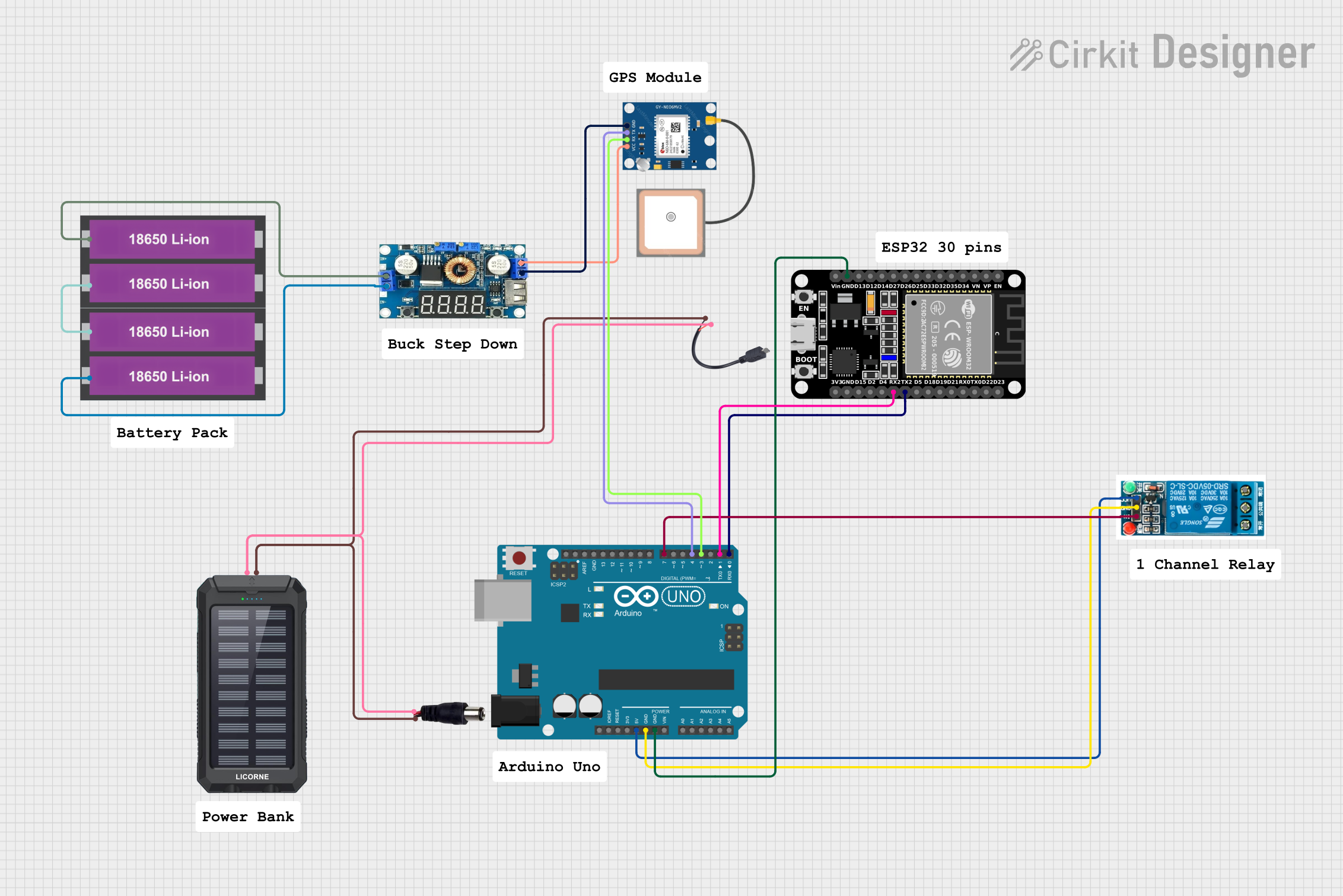
Circuit Documentation
Summary
This document provides a detailed overview of a circuit that integrates an ESP32 microcontroller, an Arduino UNO, a GPS module, a 5V relay, a step-down voltage regulator, 18650 Li-ion batteries, a solar charger power bank, and various connectors. The circuit is designed to facilitate communication between the ESP32 and Arduino UNO, power management, and GPS data acquisition.
Component List
ESP32 (30 pin)
- Description: A versatile microcontroller with built-in Wi-Fi and Bluetooth capabilities.
- Pins: EN, VP, VN, D34, D35, D32, D33, D25, D26, D27, D14, D12, D13, GND, Vin, D23, D22, TX0, RX0, D21, D19, D18, D5, TX2, RX2, D4, D2, D15, 3V3
Arduino UNO
- Description: A popular microcontroller board based on the ATmega328P.
- Pins: UNUSED, IOREF, Reset, 3.3V, 5V, GND, Vin, A0, A1, A2, A3, A4, A5, SCL, SDA, AREF, D13, D12, D11, D10, D9, D8, D7, D6, D5, D4, D3, D2, D1, D0
GPS NEO 6M
- Description: A GPS module for acquiring location data.
- Pins: VCC, RX, TX, GND
Regulator Stepdown DC with LCD Display
- Description: A step-down voltage regulator with an LCD display for monitoring output voltage.
- Pins: IN +, IN -, OUT +, OUT -
18650 Li-ion Battery x 2
- Description: Rechargeable lithium-ion batteries.
- Pins: +, -
5V Relay
- Description: An electromechanical relay for switching applications.
- Pins: Normally Open, Common terminal, Normally Closed, In, GND, VCC
Solar Charger Power Bank
- Description: A power bank with solar charging capabilities.
- Pins: +, -
Power Jack
- Description: A connector for external power supply.
- Pins: POSITIF, NEGATIF
Micro USB to Cable (2 Pin)
- Description: A micro USB connector with two output pins.
- Pins: Micro USB, +, -
Wiring Details
ESP32 (30 pin)
- GND connected to Arduino UNO GND
- TX2 connected to Arduino UNO D0
- RX2 connected to Arduino UNO D1
Arduino UNO
- GND connected to ESP32 GND
- D0 connected to ESP32 TX2
- D1 connected to ESP32 RX2
- 5V connected to 5V Relay VCC
- GND connected to 5V Relay GND
- D7 connected to 5V Relay In
- D4 connected to GPS NEO 6M TX
- D3 connected to GPS NEO 6M RX
GPS NEO 6M
- VCC connected to Regulator Stepdown DC with LCD Display OUT +
- RX connected to Arduino UNO D3
- TX connected to Arduino UNO D4
- GND connected to Regulator Stepdown DC with LCD Display OUT -
Regulator Stepdown DC with LCD Display
- OUT + connected to GPS NEO 6M VCC
- OUT - connected to GPS NEO 6M GND
- IN + connected to 18650 Li-ion Battery x 2 +
- IN - connected to 18650 Li-ion Battery x 2 -
18650 Li-ion Battery x 2
- + connected to Regulator Stepdown DC with LCD Display IN +
- - connected to Regulator Stepdown DC with LCD Display IN -
- + connected to 18650 Li-ion Battery x 2 -
5V Relay
- VCC connected to Arduino UNO 5V
- GND connected to Arduino UNO GND
- In connected to Arduino UNO D7
Solar Charger Power Bank
- + connected to Micro USB to Cable (2 Pin) + and Power Jack POSITIF
- - connected to Micro USB to Cable (2 Pin) - and Power Jack NEGATIF
Power Jack
- POSITIF connected to Solar Charger Power Bank +
- NEGATIF connected to Solar Charger Power Bank -
Micro USB to Cable (2 Pin)
- + connected to Solar Charger Power Bank +
- - connected to Solar Charger Power Bank -
Documented Code
Arduino UNO Code (sketch.ino)
void setup() {
  // put your setup code here, to run once:

}

void loop() {
  // put your main code here, to run repeatedly:

}
Additional Documentation (documentation.txt)
This document provides a comprehensive overview of the circuit, including component descriptions, wiring details, and the code used in the microcontrollers.