
Arduino and SIM900A GSM Module SMS Alert System with Buzzer Notification
View and Edit Project In Cirkit Designer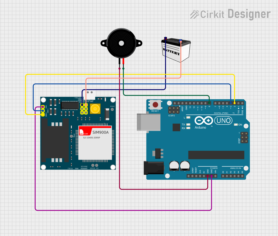
Circuit Documentation
Summary
This circuit integrates an Arduino UNO microcontroller, a SIM900A GSM module, a 12V battery, and a Piezo speaker. The primary function of the circuit is to send an SMS notification and activate a buzzer when a specific condition is met. The Arduino UNO controls the GSM module and the Piezo speaker.
Component List
SIM900A
- Description: GSM module used for sending SMS notifications.
- Pins: GND, DB9-3 (RXD), DB9-2 (TXD), 5V, 3VR, 5VR, 3VT, 5VT, VCC, Ring, RESTART, RESET, STATUS
Arduino UNO
- Description: Microcontroller used to control the GSM module and the Piezo speaker.
- Pins: UNUSED, IOREF, Reset, 3.3V, 5V, GND, Vin, A0, A1, A2, A3, A4, A5, SCL, SDA, AREF, D13, D12, D11, D10, D9, D8, D7, D6, D5, D4, D3, D2, D1, D0
12V Battery (Small Size)
- Description: Power source for the circuit.
- Pins: VCC, GND
Piezo Speaker
- Description: Buzzer used to signal that an SMS has been sent.
- Pins: pin1, pin2
Wiring Details
SIM900A
- GND: Connected to GND of Arduino UNO and GND of 12V Battery.
- DB9-3 (RXD): Connected to D3 of Arduino UNO.
- DB9-2 (TXD): Connected to D2 of Arduino UNO.
- VCC: Connected to VCC of 12V Battery.
Arduino UNO
- GND: Connected to GND of SIM900A and pin1 of Piezo Speaker.
- D3: Connected to DB9-3 (RXD) of SIM900A.
- D2: Connected to DB9-2 (TXD) of SIM900A.
- D8: Connected to pin2 of Piezo Speaker.
12V Battery (Small Size)
- GND: Connected to GND of SIM900A.
- VCC: Connected to VCC of SIM900A.
Piezo Speaker
- pin1: Connected to GND of Arduino UNO.
- pin2: Connected to D8 of Arduino UNO.
Documented Code
#include <SoftwareSerial.h>  // For using software serial communication

// Pin configuration
#define BUZZER_PIN 8          // Buzzer connected to pin 8

// Initialize SoftwareSerial for GSM module (TX to Pin 2, RX to Pin 3)
SoftwareSerial gsmSerial(2, 3);  // RX, TX

void setup() {
  // Start serial communication for debugging
  Serial.begin(9600);            // Start Serial Monitor at 9600 baud rate
  gsmSerial.begin(9600);         // Start GSM serial at 9600 baud rate

  // Setup buzzer
  pinMode(BUZZER_PIN, OUTPUT);

  // Wait for GSM module to initialize
  Serial.println("Initializing GSM module...");
  delay(1000);

  // Check if GSM module is connected
  gsmSerial.println("AT");
  delay(1000);
  if (gsmSerial.available()) {
    Serial.println("GSM Module is ready!");
  } else {
    Serial.println("Error: GSM Module not detected!");
  }

  // Send SMS notification setup
  gsmSerial.println("AT+CMGF=1"); // Set GSM module to text mode
  delay(1000);

  // Replace with your own phone number
  String phoneNumber = "+1234567890";  // Enter the phone number where you want the SMS to be sent

  // Send the SMS message
  gsmSerial.print("AT+CMGS=\"");
  gsmSerial.print(phoneNumber);
  gsmSerial.println("\"");
  delay(1000);
  gsmSerial.println("Detection Alert! This is your SMS notification.");
  gsmSerial.write(26);  // ASCII value for Ctrl+Z to send the SMS
  delay(1000);

  // Activate buzzer to signal SMS has been sent
  digitalWrite(BUZZER_PIN, HIGH);  // Turn on buzzer
  delay(500);                      // Wait for half a second
  digitalWrite(BUZZER_PIN, LOW);   // Turn off buzzer

  // End the program after sending SMS
  Serial.println("SMS sent!");
}

void loop() {
  // In a real-world application, you would have a sensor or condition to trigger the SMS.
  // For testing purposes, this code sends a single SMS in the setup() function.
}
This code initializes the GSM module and sends an SMS notification to a predefined phone number. It also activates a buzzer to signal that the SMS has been sent. The code runs once during the setup phase and does not repeat in the loop.