
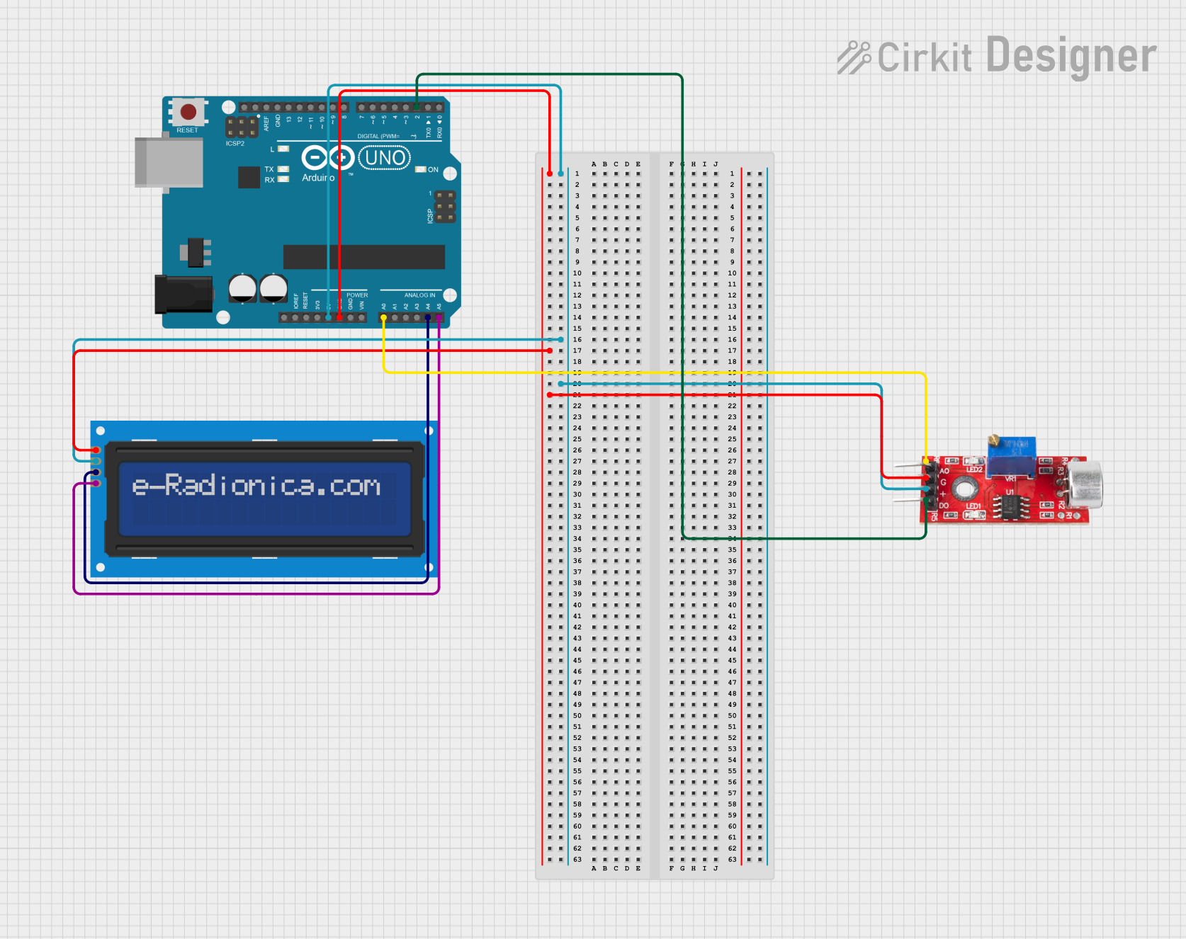
Circuit Documentation
Summary
This circuit is designed to detect noise levels using a sound sensor and display the results on a 16x2 I2C LCD screen. The core of the circuit is an Arduino UNO microcontroller, which reads the analog signal from the sound sensor and processes it to determine the noise level. The results are then displayed on the LCD screen.
Component List
Sound Sensor
- Pins: Analog, GND, VCC, Digital
- Description: A sensor that detects sound levels and outputs an analog signal proportional to the sound intensity.
- Purpose in Circuit: To detect noise levels and provide an analog signal to the Arduino for processing.
LCD screen 16x2 I2C
- Pins: SCL, SDA, VCC, GND
- Description: A 16x2 character LCD screen with I2C interface.
- Purpose in Circuit: To display the noise level or a warning message based on the sound sensor's readings.
Arduino UNO
- Pins: UNUSED, IOREF, Reset, 3.3V, 5V, GND, Vin, A0, A1, A2, A3, A4, A5, SCL, SDA, AREF, D13, D12, D11, D10, D9, D8, D7, D6, D5, D4, D3, D2, D1, D0
- Description: A microcontroller board based on the ATmega328P.
- Purpose in Circuit: To read the analog signal from the sound sensor, process the data, and control the LCD screen to display the results.
Wiring Details
Sound Sensor
- Analog Pin connected to Arduino UNO A0
- GND Pin connected to Arduino UNO GND
- VCC Pin connected to Arduino UNO 5V
- Digital Pin connected to Arduino UNO D2
LCD screen 16x2 I2C
- SCL Pin connected to Arduino UNO A5
- SDA Pin connected to Arduino UNO A4
- GND Pin connected to Arduino UNO GND
- VCC Pin connected to Arduino UNO 5V
Arduino UNO
- A0 Pin connected to Sound Sensor Analog Pin
- D2 Pin connected to Sound Sensor Digital Pin
- A5 Pin connected to LCD screen 16x2 I2C SCL Pin
- A4 Pin connected to LCD screen 16x2 I2C SDA Pin
- GND Pin connected to Sound Sensor GND Pin and LCD screen 16x2 I2C GND Pin
- 5V Pin connected to Sound Sensor VCC Pin and LCD screen 16x2 I2C VCC Pin
Code Documentation
#include <Wire.h>
#include <LiquidCrystal_I2C.h>

// Initialize the I2C LCD (Address: 0x27, 16 columns, 2 rows)
LiquidCrystal_I2C lcd(0x27, 16, 2);

// Define the pin for the sound sensor
const int soundSensorPin = A0;

// Define a noise threshold for a library (adjust this based on testing)
const int noiseThreshold = 100;  // Lower threshold for quiet environments

void setup() {
  // Initialize the LCD
  lcd.init();
  lcd.backlight();

  // Print a message on the LCD
  lcd.setCursor(0, 0);
  lcd.print("Noise Detection");

  // Set up the sound sensor pin
  pinMode(soundSensorPin, INPUT);
}

void loop() {
  // Take multiple readings to smooth data
  int soundLevel = 0;
  for (int i = 0; i < 10; i++) {
    soundLevel += analogRead(soundSensorPin);
    delay(5);  // Small delay between readings
  }
  soundLevel = soundLevel / 10;  // Average the readings

  // Clear the second line of the LCD
  lcd.setCursor(0, 1);
  lcd.print("                "); // Clear previous data

  // Display noise level or warning message
  lcd.setCursor(0, 1);
  if (soundLevel > noiseThreshold) {
    lcd.print("Noise Detected!");
  } else {
    lcd.print("Quiet Environment");
  }

  // Optional: Add a small delay
  delay(200);
}
This code initializes the LCD screen and sets up the sound sensor pin. In the loop function, it reads the sound level multiple times to smooth the data, averages the readings, and then displays either "Noise Detected!" or "Quiet Environment" on the LCD screen based on the noise threshold.