
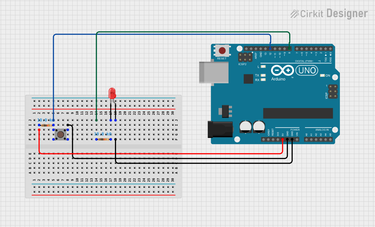
Circuit Documentation
Summary of the Circuit
This circuit is designed around an Arduino UNO microcontroller and includes a pushbutton, two resistors, and a red two-pin LED. The pushbutton is used to input a signal to the Arduino, which then controls the LED based on the button's state. The resistors are used to limit current: one is connected to the pushbutton and the other is in series with the LED. The Arduino UNO reads the state of the pushbutton and outputs a signal to the LED, turning it on or off accordingly.
Component List
Arduino UNO
- Description: A microcontroller board based on the ATmega328P.
- Pins: UNUSED, IOREF, Reset, 3.3V, 5V, GND, Vin, A0-A5, SCL, SDA, AREF, D0-D13.
LED: Two Pin (red)
- Description: A basic red LED.
- Pins: Anode, Cathode.
Pushbutton
- Description: A simple pushbutton switch.
- Pins: Pin 1 (in), Pin 2 (in), Pin 3 (out), Pin 4 (out).
Resistor (10k Ohms)
- Description: A resistor with a resistance of 10,000 Ohms.
- Pins: Pin1, Pin2.
Wiring Details
Arduino UNO
- 5V connected to one end of a 10k Ohm resistor.
- D12 connected to the other end of the same 10k Ohm resistor and to one pair of pushbutton pins (Pin 1 (in) and Pin 3 (out)).
- GND connected to the other pair of pushbutton pins (Pin 2 (in) and Pin 4 (out)).
- D8 connected to one end of another 10k Ohm resistor.
- GND also connected to the anode of the red LED.
LED: Two Pin (red)
- Cathode connected to one end of a 10k Ohm resistor.
- Anode connected to GND on the Arduino UNO.
Pushbutton
- Pin 1 (in) and Pin 3 (out) connected to D12 on the Arduino UNO and to one end of a 10k Ohm resistor.
- Pin 2 (in) and Pin 4 (out) connected to GND on the Arduino UNO.
Resistor (10k Ohms)
- One resistor has pin1 connected to 5V on the Arduino UNO and pin2 connected to D12 on the Arduino UNO and to the pushbutton.
- The other resistor has pin1 connected to D8 on the Arduino UNO and pin2 connected to the cathode of the red LED.
Documented Code
// Define pin connections
int LEDPin = 8;      // LED connected to digital pin 8
int buttonPin = 12;   // Button connected to digital pin 12
int buttonRead;       // Variable to store button state
int DelayTime = 500;  // Delay time in milliseconds

// Setup function runs once at the start
void setup() {
  Serial.begin(9600);          // Start serial communication at 9600 baud
  pinMode(LEDPin, OUTPUT);     // Set LED pin as an output
  pinMode(buttonPin, INPUT);   // Set button pin as an input
}

// Loop function runs repeatedly
void loop() {
  buttonRead = digitalRead(buttonPin);  // Read the button state
  Serial.println(buttonRead);           // Print the button state to the serial monitor
  delay(DelayTime);                     // Wait for a specified time
}
The code sets up the Arduino UNO to read the state of the pushbutton and print it to the serial monitor. The LED is controlled by the digital pin 8, and the pushbutton state is read from digital pin 12. The DelayTime variable introduces a half-second delay between each read of the button state.