
Arduino-Controlled Conveyor Belt and Water Pump System with Piezoelectric Sensors
View and Edit Project In Cirkit Designer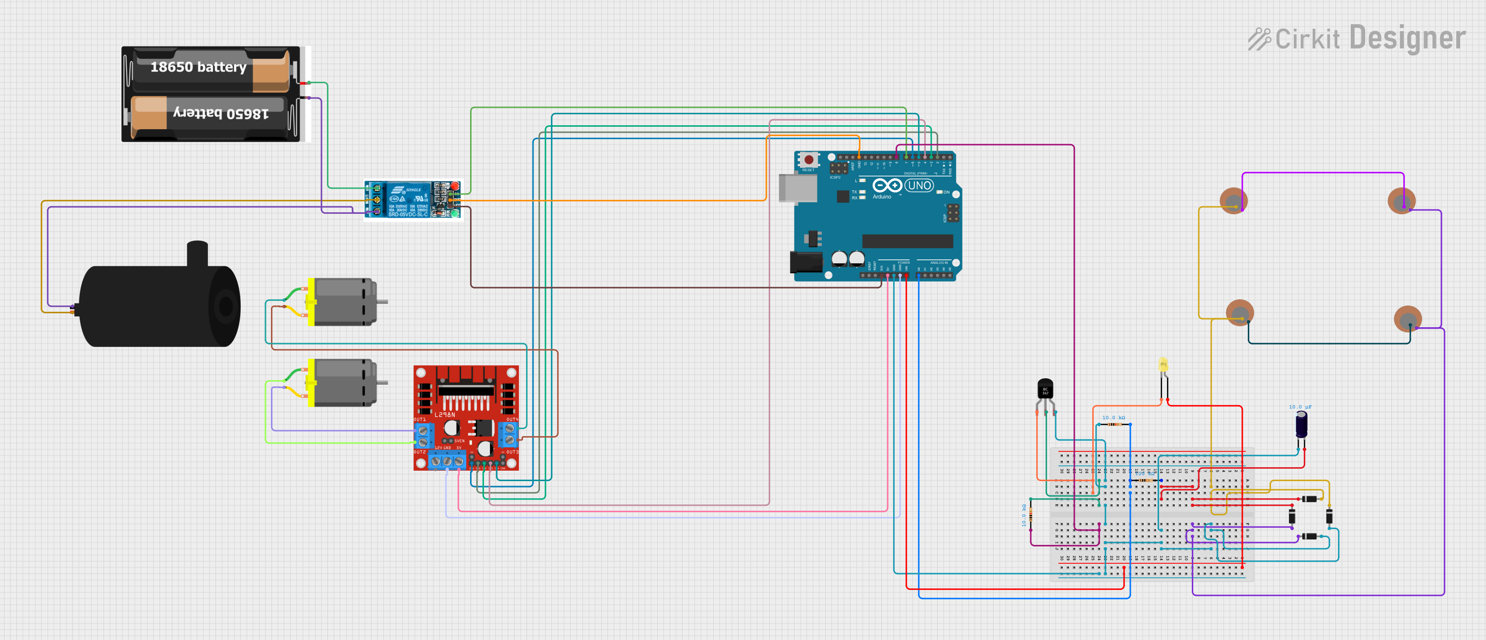
Circuit Documentation
Summary
The circuit in question appears to be designed for a system that involves motion control and fluid pumping, likely part of a larger automated or semi-automated process. It includes two DC motors controlled by an L298N motor driver, a water pump controlled by a 5V relay, multiple piezo sensors for input, and an Arduino UNO microcontroller for control logic. The circuit also includes power supply components, protective diodes, a transistor for LED control, and resistors for current limiting and pull-down purposes.
Component List
DC Motor
- Description: Electric motor that converts DC electrical power into mechanical rotation.
- Purpose: Typically used for driving mechanical systems like wheels, conveyors, or fans.
5V Relay
- Description: An electromechanical switch that allows a low-power signal to control a higher power circuit.
- Purpose: Used to control the water pump, isolating the microcontroller from the higher power required by the pump.
Piezo Sensor
- Description: A sensor that generates an electrical charge in response to applied mechanical stress.
- Purpose: Likely used as an input device to detect vibrations or pressure changes.
2x 18650 Battery Pack
- Description: A power source consisting of two 18650 lithium-ion cells.
- Purpose: Provides power to the circuit.
Water Pump
- Description: A device that moves fluids by mechanical action.
- Purpose: Used to pump water or other fluids as part of the system's operation.
L298N DC Motor Driver
- Description: An integrated circuit that allows control of two DC motors.
- Purpose: Drives the DC motors based on signals from the microcontroller.
Arduino UNO
- Description: A microcontroller board based on the ATmega328P.
- Purpose: Acts as the brain of the circuit, controlling the motors, reading sensors, and managing the relay.
Diode
- Description: A semiconductor device that allows current to flow in one direction only.
- Purpose: Provides reverse voltage protection and ensures current flow direction.
Electrolytic Capacitor
- Description: A polarized capacitor with a relatively high capacitance value.
- Purpose: Used for filtering and stabilizing the DC power supply.
Resistor
- Description: A passive two-terminal electrical component that implements electrical resistance.
- Purpose: Used for current limiting, voltage division, and pull-down configurations.
BC547 Transistor
- Description: A general-purpose NPN bipolar junction transistor.
- Purpose: Used to switch or amplify electronic signals.
LED (Yellow)
- Description: A light-emitting diode that emits yellow light when forward-biased.
- Purpose: Acts as an indicator light in the circuit.
Wiring Details
DC Motor
- Connected to the L298N motor driver's output pins to receive control signals for operation.
5V Relay
- The Normally Open (NO) contact is connected to the positive terminal of the battery pack.
- The Common terminal is connected to the positive terminal of the water pump.
- The Normally Closed (NC) contact is connected to the ground of the battery pack and the negative terminal of the water pump.
- The input signal pin (In) is connected to a digital pin on the Arduino UNO for control.
- The ground (GND) is connected to the Arduino UNO's ground.
- The VCC is connected to the 3.3V output from the Arduino UNO.
Piezo Sensor
- Connected in a network with other piezo sensors and diodes to form a sensing array.
2x 18650 Battery Pack
- Provides VCC and GND to the relay and the water pump.
Water Pump
- Connected to the relay to be switched on and off by the control signal from the Arduino UNO.
L298N DC Motor Driver
- Receives control signals from the Arduino UNO to drive the DC motors.
- Connected to the Arduino UNO for power (5V) and ground (GND).
- Motor control inputs (IN1, IN2, IN3, IN4) are connected to digital pins on the Arduino UNO.
- Motor outputs (OUT1, OUT2, OUT3, OUT4) are connected to the DC motors.
Arduino UNO
- Controls the relay, motor driver, and reads the piezo sensors.
- Provides power to the relay and motor driver.
- Digital and analog pins are used for interfacing with the relay, motor driver, and sensors.
Diode
- Connected in series with piezo sensors and across the relay coil for protection against reverse currents.
Electrolytic Capacitor
- Connected across the power supply lines for filtering.
Resistor
- Connected to the Arduino UNO for pull-down configurations and current limiting.
BC547 Transistor
- Used to control the LED based on signals from the Arduino UNO.
LED (Yellow)
- Connected to the collector of the BC547 transistor and powered by the Arduino UNO's Vin pin through a current-limiting resistor.
Documented Code
#include <Wire.h>
#include <LiquidCrystal_I2C.h>

// Define the LCD address, for a 16x2 LCD
LiquidCrystal_I2C lcd(0x27, 16, 2);

// Pin assignments for garbage collector
int relayPin = 7;  // Relay connected to digital pin 7 (controls water pump)
int motorIn1 = 2;  // Motor driver IN1 for conveyor belt motor 1
int motorIn2 = 3;  // Motor driver IN2 for conveyor belt motor 1
int motorIn3 = 4;  // Motor driver IN3 for conveyor belt motor 2
int motorIn4 = 5;  // Motor driver IN4 for conveyor belt motor 2
int motorSpeed = 6; // Motor driver ENA (PWM speed control for both motors)

// Pin assignments for piezoelectric sensor and LCD
const int piezoPin = A0;  // Piezoelectric sensor connected to A0
const int g24Pin = 8;     // G24 connected to digital pin 8

void setup() {
  // Initialize LCD
  lcd.begin();
  lcd.backlight();  // Turn on the backlight

  // Initialize Serial for debugging
  Serial.begin(9600);

  // Set pin modes for motors, relay, and piezo sensor
  pinMode(relayPin, OUTPUT);
  pinMode(motorIn1, OUTPUT);
  pinMode(motorIn2, OUTPUT);
  pinMode(motorIn3, OUTPUT);
  pinMode(motorIn4, OUTPUT);
  pinMode(motorSpeed, OUTPUT);
  pinMode(piezoPin, INPUT);
  pinMode(g24Pin, INPUT);  // Assuming G24 is a sensor input

  // Print initial message on LCD
  lcd.setCursor(0, 0);
  lcd.print("Piezo Reading:");

  // Start with motors and pump off
  digitalWrite(relayPin, LOW);
  digitalWrite(motorIn1, LOW);
  digitalWrite(motorIn2, LOW);
  digitalWrite(motorIn3, LOW);
  digitalWrite(motorIn4, LOW);
  analogWrite(motorSpeed, 0);  // Motor speed set to 0
}

void loop() {
  // Read the piezoelectric sensor value
  int piezoValue = analogRead(piezoPin);
  int g24State = digitalRead(g24Pin);

  // Print piezo value to Serial Monitor
  Serial.print("Piezoelectric Value: ");
  Serial.println(piezoValue);

  // Display piezoelectric sensor value on the LCD
  lcd.setCursor(0, 1);
  lcd.print("Value: ");
  lcd.print(piezoValue);
  lcd.print("   ");  // Clear leftover characters

  // If piezo sensor detects sufficient pressure or G24 is HIGH, run motors
  if (piezoValue > 100 || g24State == HIGH) {
    // Run conveyor belt motors forward
    digitalWrite(motorIn1, HIGH);
    digitalWrite(motorIn2, LOW);
    digitalWrite(motorIn3, HIGH);
    digitalWrite(motorIn4, LOW);
    analogWrite(motorSpeed, 255);  // Full speed

    // Turn on the water pump
    digitalWrite(relayPin, HIGH);  // Water pump ON
  } else {
    // Stop everything if no piezoelectric reading or G24 is LOW
    digitalWrite(relayPin, LOW);  // Turn off water pump
    analogWrite(motorSpeed, 0);   // Stop conveyor motors
  }

  delay(500);  // Small delay before next reading
}
This code is designed to run on an Arduino UNO and controls the motors, relay, and reads the piezo sensors. It also includes an LCD display for showing sensor readings. The code is structured with setup and loop functions, typical for Arduino sketches. The setup function initializes the LCD, serial communication, and pin modes, while the loop function reads sensor values, controls the motors and relay, and updates the LCD display.