
Arduino Uno R3 Multi-Sensor Monitoring System with Data Logging and Audio Alerts
View and Edit Project In Cirkit Designer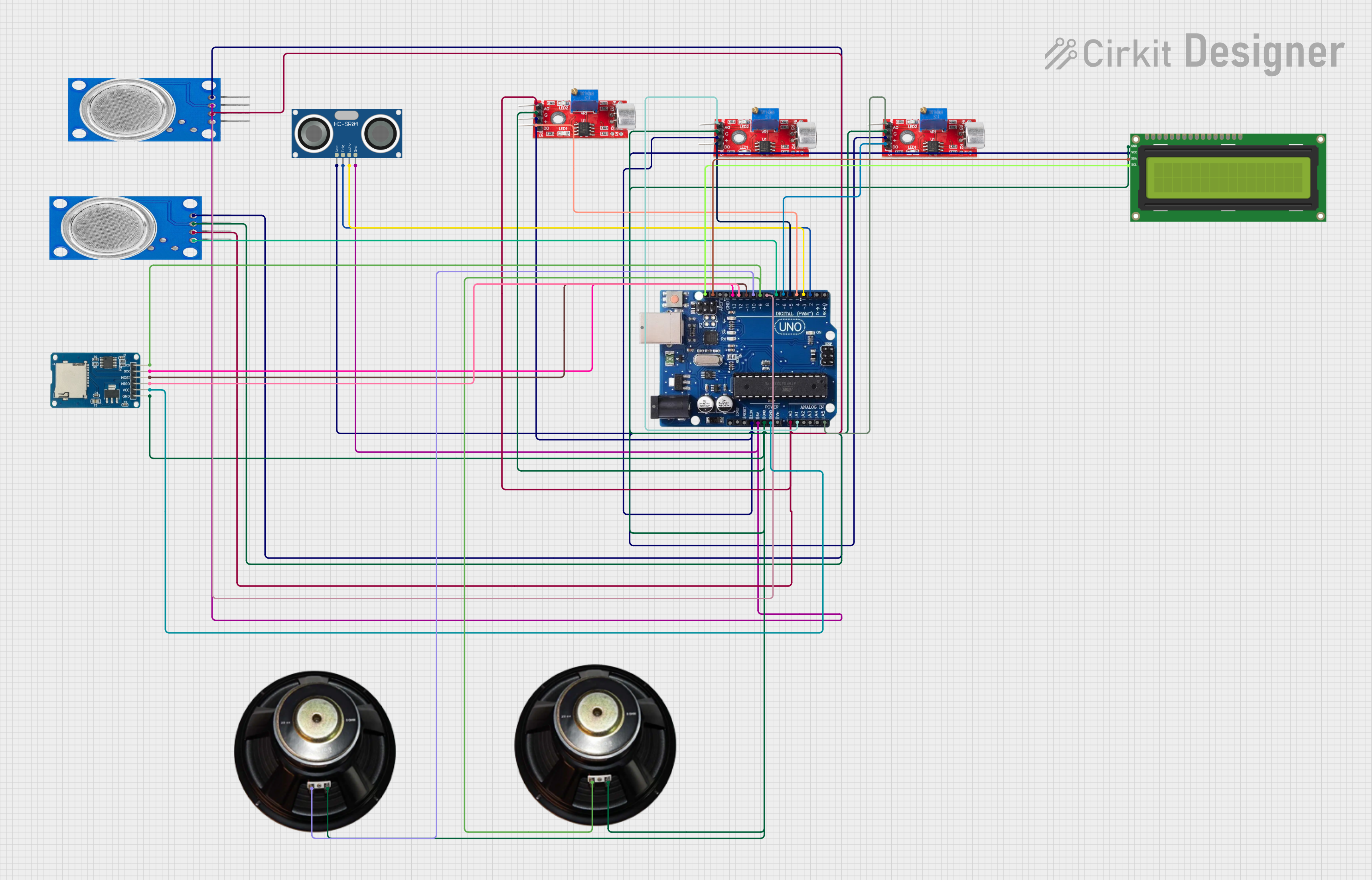
Circuit Documentation
Summary
This circuit integrates various sensors, output devices, and a microcontroller to form a multifunctional system. The core of the circuit is an Arduino Uno R3, which interfaces with sound sensors, an ultrasonic sensor (HC-SR04), gas sensors (MQ135), an I2C LCD screen, a micro SD card module, and speakers. The sensors collect environmental data, the LCD displays information, the SD card module facilitates data logging, and the speakers provide audio output. The circuit is powered through the Arduino's voltage regulators, with components connected to either the 3.3V or 5V supply lines.
Component List
Arduino Uno R3: A microcontroller board based on the ATmega328P. It has digital input/output pins, analog inputs, a USB connection for programming, and power jacks.
Sound Sensor: A device that detects sound levels in the environment and provides both analog and digital outputs.
HC-SR04 Ultrasonic Sensor: An ultrasonic distance sensor that provides distance measurements by emitting ultrasonic waves and measuring the time taken for the echo to return.
MQ135 Gas Sensor: A sensor for detecting the presence of various gases in the air, including harmful pollutants.
I2C LCD 16x2 Screen: A liquid crystal display that can show 16 characters per line on 2 lines, interfaced via the I2C protocol.
Micro SD Card Module: A module that allows micro SD cards to be read from and written to, typically used for data logging.
Speaker: An electroacoustic transducer that converts electrical audio signals into sound waves.
Wiring Details
Arduino Uno R3
Power Supply:
- 3.3V pin connected to the Micro SD Card Module.
- 5V pin connected to Sound Sensors, HC-SR04 Ultrasonic Sensor, I2C LCD Screen, and MQ135 Gas Sensors.
- GND pins connected to various components for a common ground reference.
Digital/Analog Pins:
- A0 connected to MQ135 Gas Sensors and a Sound Sensor.
- A1 connected to a Sound Sensor.
- A5/SCL connected to a Sound Sensor.
- SCL connected to the I2C LCD Screen.
- SDA connected to the I2C LCD Screen.
- Pins 2-13 connected to various components including the Micro SD Card Module, Speakers, MQ135 Gas Sensors, Sound Sensors, and the HC-SR04 Ultrasonic Sensor.
Sound Sensor
- Analog Output:
- Connected to Arduino Uno R3 analog pins (A0, A1, A5/SCL) for analog sound level readings.
- Digital Output:
- Connected to Arduino Uno R3 digital pins (4, 5, 6) for digital sound detection signals.
- Power:
- VCC connected to the 5V supply from the Arduino Uno R3.
- GND connected to the common ground.
HC-SR04 Ultrasonic Sensor
- TRIG:
- Connected to Arduino Uno R3 pin 2 for triggering ultrasonic pulses.
- ECHO:
- Connected to Arduino Uno R3 pin 3 for receiving the echo signal.
- Power:
- VCC connected to the 5V supply from the Arduino Uno R3.
- GND connected to the common ground.
MQ135 Gas Sensor
- Analog Output (A0):
- Connected to Arduino Uno R3 analog pin A0 for gas concentration readings.
- Digital Output (D0):
- Connected to Arduino Uno R3 digital pins 7 and 8 for threshold-based gas detection.
- Power:
- VCC connected to the 5V supply from the Arduino Uno R3.
- GND connected to the common ground.
I2C LCD 16x2 Screen
- SCL:
- Connected to Arduino Uno R3 SCL pin for I2C clock signal.
- SDA:
- Connected to Arduino Uno R3 SDA pin for I2C data signal.
- Power:
- VCC (5V) connected to the 5V supply from the Arduino Uno R3.
- GND connected to the common ground.
Micro SD Card Module
- cs:
- Connected to Arduino Uno R3 pin 9 for chip select signal.
- sck:
- Connected to Arduino Uno R3 pin 13 for serial clock signal.
- mosi:
- Connected to Arduino Uno R3 pin 11 for Master Out Slave In data signal.
- miso:
- Connected to Arduino Uno R3 pin 12 for Master In Slave Out data signal.
- Power:
- VCC connected to the 3.3V supply from the Arduino Uno R3.
- GND connected to the common ground.
Speaker
- + (Positive):
- Connected to Arduino Uno R3 digital pins 9 and 10 for audio signal output.
- - (Negative):
- Connected to the common ground.
Documented Code
No code was provided for the microcontrollers in the circuit. To fully utilize the hardware, embedded code should be written and uploaded to the Arduino Uno R3. The code would typically initialize the sensors, read data from them, control the output devices, and handle communication with the micro SD card module for data logging. It would also include libraries for interfacing with the I2C LCD screen and managing the file system on the SD card.