
Circuit Documentation
Summary
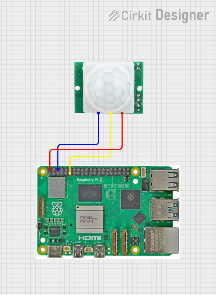
This circuit involves a Raspberry Pi 5 connected to an HC-SR501 motion sensor. The Raspberry Pi 5 provides power to the motion sensor and reads its output signal through one of its GPIO pins.
Component List
Raspberry Pi 5
- Description: A powerful single-board computer with multiple GPIO pins, USB ports, HDMI outputs, and other interfaces.
- Pins: Type-C, Micro HDMI 1, Micro HDMI 2, Camera 1, Camera 2, PoE, Fan, PCIe, USB 3.0, USB 2.0, Ethernet, 5V, GND, 3.3v, GPIO 14, GPIO 15, GPIO 18, GPIO 23, GPIO 24, GPIO 25, GPIO 8, GPIO 7, GPIO 1, GPIO 12, GPIO 16, GPIO 20, GPIO 21, GPIO 2, GPIO 3, GPIO 4, GPIO 17, GPIO 27, GPIO 22, GPIO 10, GPIO 9, GPIO 11, GPIO 0, GPIO 5, GPIO 6, GPIO 13, GPIO 19, GPIO 26
- Purpose in Circuit: Acts as the main controller and power source for the motion sensor.
HC-SR501 Motion Sensor
- Description: A passive infrared (PIR) sensor used to detect motion.
- Pins: GND, OUT, VCC
- Purpose in Circuit: Detects motion and sends a signal to the Raspberry Pi.
Wiring Details
Raspberry Pi 5
- 5V: Connected to VCC of the HC-SR501 Motion Sensor
- GND: Connected to GND of the HC-SR501 Motion Sensor
- GPIO 17: Connected to OUT of the HC-SR501 Motion Sensor
HC-SR501 Motion Sensor
- VCC: Connected to 5V of the Raspberry Pi 5
- GND: Connected to GND of the Raspberry Pi 5
- OUT: Connected to GPIO 17 of the Raspberry Pi 5
Code
No code is provided for this circuit.