
ESP8266-Based Woman Safety Device with OLED Display and GSM Alert
View and Edit Project In Cirkit Designer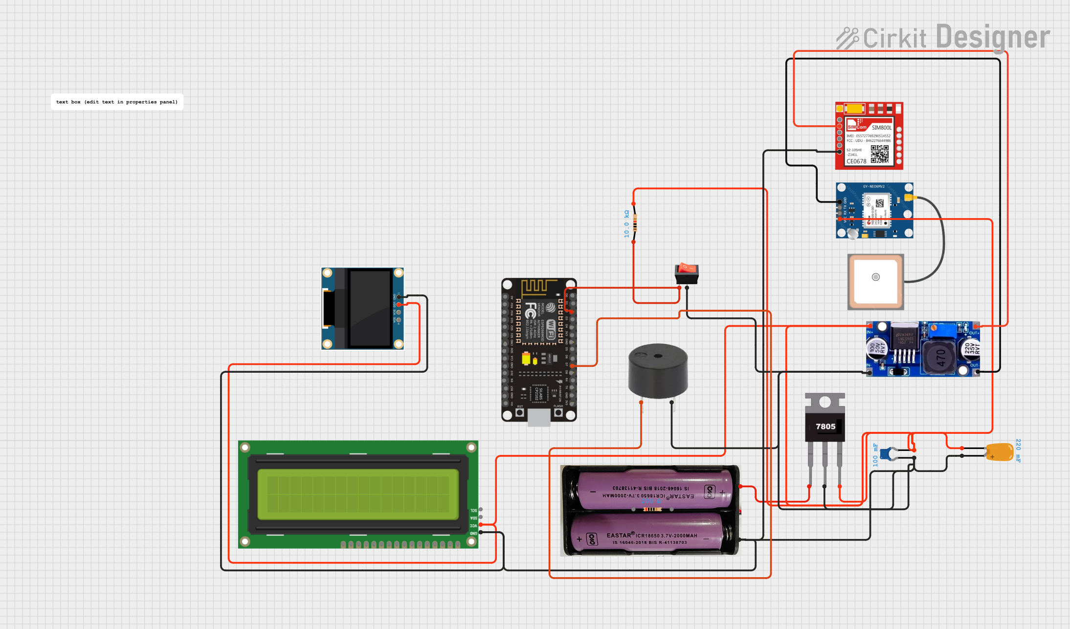
Circuit Documentation
Summary
This document provides a detailed overview of a woman safety device circuit. The circuit includes various components such as a NodeMCU ESP8266, OLED Display, SIM800L GSM Module, Neo6MV2 GPS Module, Buzzer, and other supporting components. The device is designed to send an alert message when a switch is activated.
Component List
esp8266 nodemcu
- Description: Microcontroller with Wi-Fi capabilities.
- Pins: D0, D1, D2, D3, D4, 3V3, GND, D5, D6, D7, D8, RX, TX, A0, RSV, SD3, SD2, SD1, CMD, SD0, CLK, EN, RST, VIN
7.4v Battery
- Description: Power source.
- Pins: +, -
7805 Voltage Regulator
- Description: Regulates voltage to 5V.
- Pins: Vin, Gnd, Vout
Ceramic Capacitor
- Description: Capacitor with 0.1 Farads capacitance.
- Pins: pin0, pin1
Tantalum Capacitor
- Description: Capacitor with 0.22 Farads capacitance.
- Pins: -, +
0.96" OLED
- Description: OLED display.
- Pins: GND, VDD, SCK, SDA
I2C LCD 16x2 Screen
- Description: LCD screen with I2C interface.
- Pins: SCL, SDA, VCC (5V), GND, VDD, VO, RS, RW, E, D0, D1, D2, D3, D4, D5, D6, D7, BLA, BLK
Sim800l
- Description: GSM module.
- Pins: NET, RST, VCC, RXD, TXD, GND
GPS NEO 6M
- Description: GPS module.
- Pins: VCC, RX, TX, GND
LM2596
- Description: DC-DC buck converter.
- Pins: IN, OUT
Rocker Switch
- Description: Switch to control the circuit.
- Pins: output, input
Buzzer
- Description: Sound alert device.
- Pins: PIN, GND
Resistor (200 Ohms)
- Description: Resistor with 200 Ohms resistance.
- Pins: pin1, pin2
Resistor (10000 Ohms)
- Description: Resistor with 10000 Ohms resistance.
- Pins: pin1, pin2
Wiring Details
esp8266 nodemcu
- D2: Connected to pin1 of 10000 Ohms Resistor and input of Rocker Switch.
- D7: Connected to PIN of Buzzer.
7.4v Battery
- +: Connected to Vin of 7805 Voltage Regulator.
- -: Connected to + of Tantalum Capacitor, GND of I2C LCD 16x2 Screen, GND of Sim800l, GND of Buzzer, output of Rocker Switch, IN of LM2596, pin0 of Ceramic Capacitor, GND of 0.96" OLED, and Gnd of 7805 Voltage Regulator.
7805 Voltage Regulator
- Vin: Connected to + of 7.4v Battery.
- Gnd: Connected to - of 7.4v Battery.
- Vout: Connected to - of Tantalum Capacitor, VCC (5V) of I2C LCD 16x2 Screen, VCC of GPS NEO 6M, IN of LM2596, pin1 of Ceramic Capacitor, and VDD of 0.96" OLED.
Ceramic Capacitor
- pin0: Connected to - of 7.4v Battery.
- pin1: Connected to Vout of 7805 Voltage Regulator.
Tantalum Capacitor
- +: Connected to - of 7.4v Battery.
- -: Connected to pin2 of 10000 Ohms Resistor.
0.96" OLED
- GND: Connected to - of 7.4v Battery.
- VDD: Connected to Vout of 7805 Voltage Regulator.
I2C LCD 16x2 Screen
- GND: Connected to - of 7.4v Battery.
- VCC (5V): Connected to Vout of 7805 Voltage Regulator.
Sim800l
- GND: Connected to - of 7.4v Battery.
- VCC: Connected to OUT of LM2596.
GPS NEO 6M
- GND: Connected to OUT of LM2596.
- VCC: Connected to Vout of 7805 Voltage Regulator.
LM2596
- IN: Connected to - of 7.4v Battery and Vout of 7805 Voltage Regulator.
- OUT: Connected to VCC of Sim800l and GND of GPS NEO 6M.
Rocker Switch
- input: Connected to pin1 of 10000 Ohms Resistor and D2 of esp8266 nodemcu.
- output: Connected to - of 7.4v Battery.
Buzzer
- PIN: Connected to D7 of esp8266 nodemcu.
- GND: Connected to - of 7.4v Battery.
Resistor (200 Ohms)
- Not connected in the provided net list.
Resistor (10000 Ohms)
- pin1: Connected to input of Rocker Switch and D2 of esp8266 nodemcu.
- pin2: Connected to - of Tantalum Capacitor.
Code Documentation
esp8266 nodemcu Code
/*
 * Woman Safety Device
 * Components: NodeMCU ESP8266, OLED Display, SIM800L GSM Module,
 * Neo6MV2 GPS Module, Buzzer, LEDs (Red, Red, Blue)
 * Functionality: This code initializes the components and provides
 * basic functionality for the safety device.
 */

#include <Wire.h>
#include <Adafruit_GFX.h>
#include <Adafruit_SSD1306.h>
#include <SoftwareSerial.h>

#define SCREEN_WIDTH 128
#define SCREEN_HEIGHT 64
#define OLED_RESET -1
Adafruit_SSD1306 display(SCREEN_WIDTH, SCREEN_HEIGHT, &Wire, OLED_RESET);

SoftwareSerial sim800l(D1, D2); // RX, TX

#define BUZZER_PIN D7
#define SWITCH_PIN D2

void setup() {
  pinMode(BUZZER_PIN, OUTPUT);
  pinMode(SWITCH_PIN, INPUT);
  digitalWrite(BUZZER_PIN, LOW);

  Serial.begin(115200);
  sim800l.begin(9600);

  if(!display.begin(SSD1306_I2C_ADDRESS, OLED_RESET)) {
    Serial.println(F("SSD1306 allocation failed"));
    for(;;);
  }
  display.display();
  delay(2000);
  display.clearDisplay();
  display.setTextSize(1);
  display.setTextColor(SSD1306_WHITE);
  display.setCursor(0, 0);
  display.println(F("Woman Safety Device"));
  display.display();
}

void loop() {
  if(digitalRead(SWITCH_PIN) == HIGH) {
    digitalWrite(BUZZER_PIN, HIGH);
    sendAlert();
  } else {
    digitalWrite(BUZZER_PIN, LOW);
  }
}

void sendAlert() {
  sim800l.println("AT+CMGF=1");
  delay(1000);
  sim800l.println("AT+CMGS=\"+1234567890\"");
  delay(1000);
  sim800l.print("Emergency! Please help.");
  delay(1000);
  sim800l.write(26);
  delay(1000);
}
0.96" OLED Code
void setup() {
  // put your setup code here, to run once:
}

void loop() {
  // put your main code here, to run repeatedly:
}
Buzzer Code
void setup() {
  // put your setup code here, to run once:
}

void loop() {
  // put your main code here, to run repeatedly:
}
This documentation provides a comprehensive overview of the circuit, including component details, wiring connections, and the code used for the microcontrollers.