
Arduino UNO-Based Smart Relay Control with INA219 Current Sensor and RGB LED
View and Edit Project In Cirkit Designer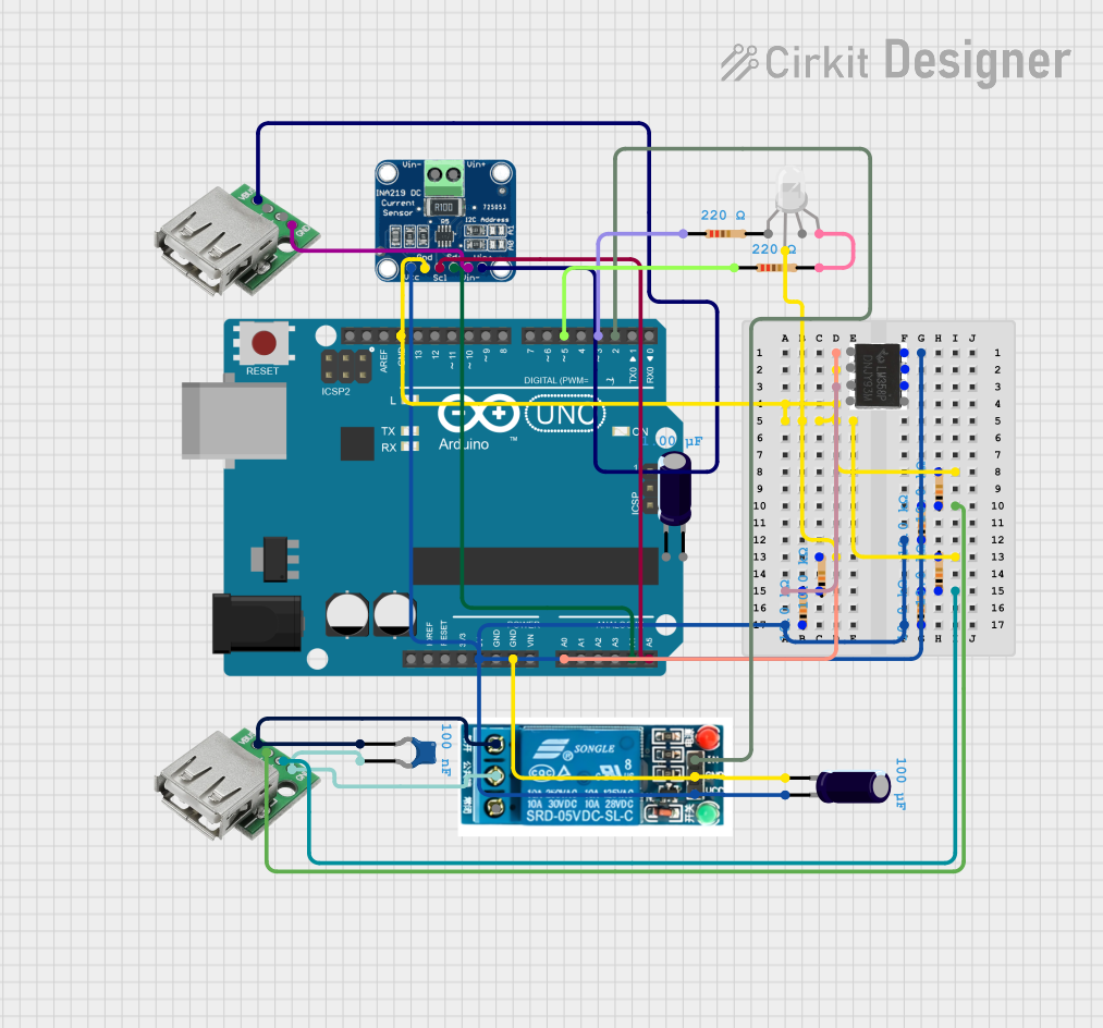
Circuit Documentation
Summary
This document provides a detailed overview of a circuit that includes an Arduino UNO microcontroller, various resistors, capacitors, a relay, an op-amp, an INA219 current sensor, an RGB LED, and USB connectors. The circuit is designed to interface with various components and perform specific functions as defined by the embedded code.
Component List
Arduino UNO
- Description: A microcontroller board based on the ATmega328P.
- Pins: UNUSED, IOREF, Reset, 3.3V, 5V, GND, Vin, A0, A1, A2, A3, A4, A5, SCL, SDA, AREF, D13, D12, D11, D10, D9, D8, D7, D6, D5, D4, D3, D2, D1, D0
USB Female
- Description: USB connector for power and data.
- Pins: VCC, GND, -D, +D
INA219
- Description: Current sensor for high-side current measurement.
- Pins: VCC, GND, SCL, SDA, VIN -, VIN +
5V Relay
- Description: Electromechanical relay for switching applications.
- Pins: Normally Open, Common terminal, Normally Closed, In, GND, VCC
LM358 Op-Amp
- Description: Operational amplifier for signal conditioning.
- Pins: 8, 1, 2, 3, 4, 5, 6, 7
Resistors
- Description: Various resistors used for current limiting and voltage division.
- Pins: pin1, pin2
- Properties:
- Resistance: 10000 Ohms
- Resistance: 220 Ohms
Electrolytic Capacitors
- Description: Capacitors for filtering and decoupling.
- Pins: -, +
- Properties:
- Capacitance: 0.0001 Farads
- Capacitance: 0.000001 Farads
Ceramic Capacitor
- Description: Capacitor for high-frequency filtering.
- Pins: pin0, pin1
- Properties:
- Capacitance: 1e-7 Farads
RGB LED (Wokwi compatible)
- Description: RGB LED for visual indication.
- Pins: R, COM, G, B
Wiring Details
Arduino UNO
- A0: No connection
- 5V: Connected to:
- Resistor pin1
- LM358 Op-Amp pin8
- Resistor pin1
- Resistor pin1
- Electrolytic Capacitor +
- INA219 VCC
- 5V Relay VCC
- GND: Connected to:
- Resistor pin2
- Resistor pin2
- Resistor pin2
- INA219 GND
- RGB LED COM
- Electrolytic Capacitor -
- 5V Relay GND
- A4: Connected to INA219 SDA
- A5: Connected to INA219 SCL
- D5: Connected to Resistor pin1
- D3: Connected to Resistor pin1
- D2: Connected to 5V Relay In
USB Female
- VCC: Connected to INA219 VIN +
- GND: Connected to INA219 VIN -
- -D: Connected to Resistor pin2
- +D: Connected to Resistor pin2
INA219
- VCC: Connected to Arduino UNO 5V
- GND: Connected to Arduino UNO GND
- SCL: Connected to Arduino UNO A5
- SDA: Connected to Arduino UNO A4
- VIN +: Connected to USB Female VCC
- VIN -: Connected to USB Female GND
5V Relay
- VCC: Connected to Arduino UNO 5V
- GND: Connected to Arduino UNO GND
- In: Connected to Arduino UNO D2
- Normally Open: Connected to Ceramic Capacitor pin0
- Common terminal: Connected to Ceramic Capacitor pin1
LM358 Op-Amp
- Pin 8: Connected to Arduino UNO 5V
Resistors
- Resistor 1:
- pin1: Connected to Arduino UNO 5V
- pin2: Connected to Resistor pin1
- Resistor 2:
- pin1: Connected to Resistor pin1
- pin2: Connected to Resistor pin2
- Resistor 3:
- pin1: Connected to Resistor pin1
- pin2: Connected to Resistor pin2
- Resistor 4:
- pin1: Connected to Resistor pin1
- pin2: Connected to Resistor pin2
- Resistor 5:
- pin1: Connected to Resistor pin1
- pin2: Connected to Resistor pin2
- Resistor 6:
- pin1: Connected to Arduino UNO D5
- pin2: Connected to RGB LED B
- Resistor 7:
- pin1: Connected to Arduino UNO D3
Electrolytic Capacitors
- Capacitor 1:
- +: Connected to Arduino UNO 5V
- -: Connected to Arduino UNO GND
- Capacitor 2:
- +: No connection
- -: No connection
Ceramic Capacitor
- pin0: Connected to USB Female VCC
- pin1: Connected to USB Female GND
RGB LED (Wokwi compatible)
- R: No connection
- COM: Connected to Arduino UNO GND
- G: No connection
- B: Connected to Resistor pin2
Documented Code
Arduino UNO Code
void setup() {
  // put your setup code here, to run once:

}

void loop() {
  // put your main code here, to run repeatedly:

}
This code is a basic template for the Arduino UNO. The setup function is used to initialize any settings or configurations, and the loop function contains the main code that runs repeatedly. Currently, both functions are empty and can be filled with the desired functionality for the circuit.