Cirkit Designer
Your all-in-one circuit design IDE
Home /
Project Documentation
Arduino Nano-Controlled Bluetooth Relay for Solenoid Lock

Circuit Documentation
Summary
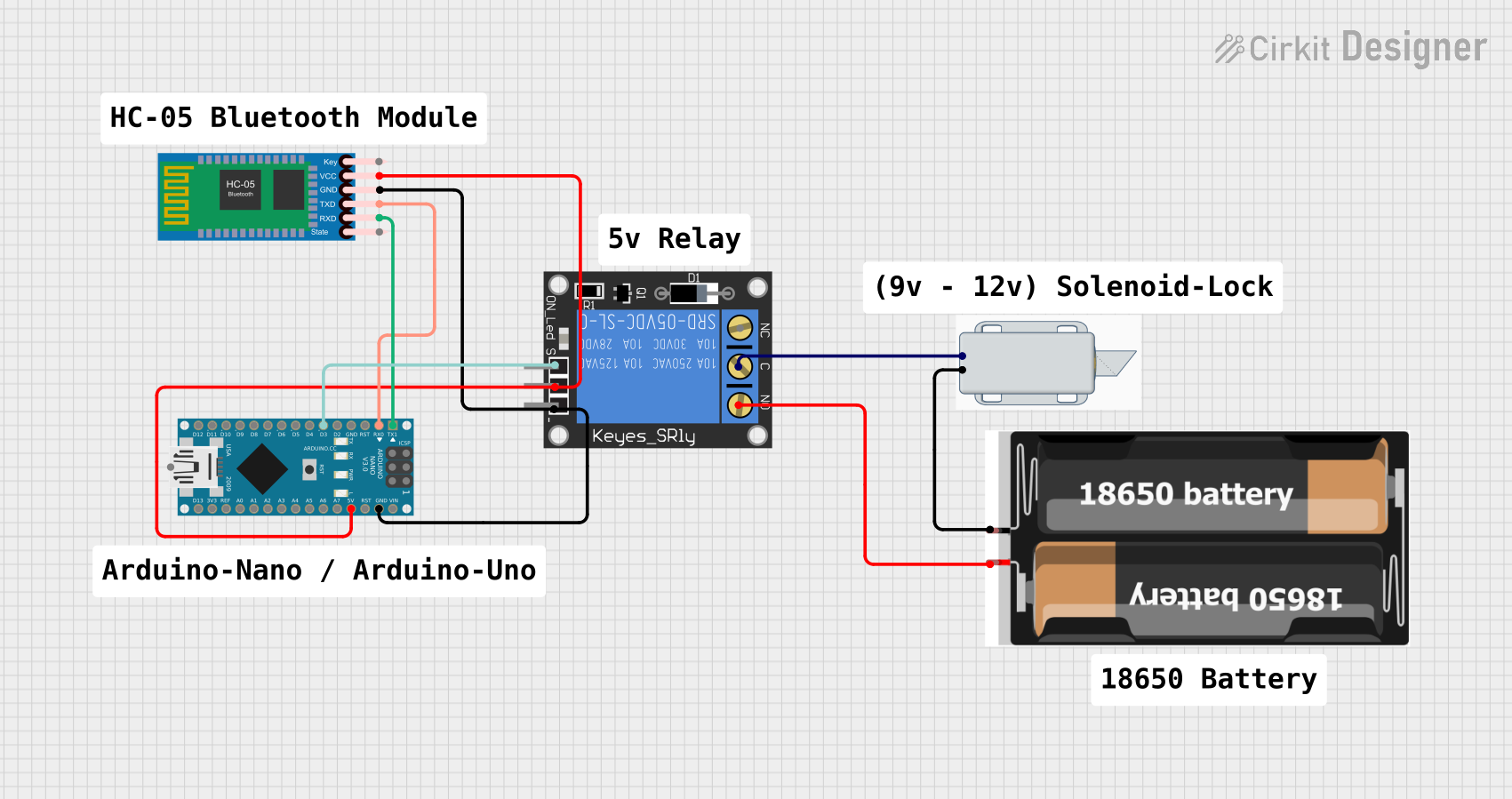
The circuit is designed to control a 12V solenoid lock using an Arduino Nano microcontroller and a 1-Channel Relay. The Arduino Nano is interfaced with an HC-05 Bluetooth Module to receive commands wirelessly. The relay acts as an electrically operated switch that controls the power to the solenoid lock. The power source for the relay and the Bluetooth module is provided by the Arduino Nano's 5V output, while the solenoid lock is powered by a separate 2x 18650 battery pack.
Component List
Arduino Nano
- Microcontroller board based on the ATmega328P.
- It has a variety of digital and analog I/O pins.
- Used for controlling the relay and communicating with the HC-05 Bluetooth module.
HC-05 Bluetooth Module
- A wireless communication module that allows for serial communication via Bluetooth.
- It is used to receive commands from a Bluetooth-enabled device to control the circuit.
1-Channel Relay (5V 10A)
- An electromechanical switch that allows for controlling high power devices with low power signals.
- In this circuit, it is used to control the power to the 12V solenoid lock.
2x 18650 Battery Pack
- A power source consisting of two 18650 lithium-ion batteries.
- Provides power to the solenoid lock.
12V Solenoid Lock
- An electrically-controlled lock that operates on 12V.
- It is the actuator in the circuit, controlled by the relay.
Wiring Details
Arduino Nano
D1/TXconnected toRXDon HC-05 Bluetooth Module.D0/RXconnected toTXDon HC-05 Bluetooth Module.D3connected tosignalon 1-Channel Relay.GNDconnected toGNDon HC-05 Bluetooth Module andgroundon 1-Channel Relay.5Vconnected toVCCon HC-05 Bluetooth Module andpoweron 1-Channel Relay.
HC-05 Bluetooth Module
RXDconnected toD1/TXon Arduino Nano.TXDconnected toD0/RXon Arduino Nano.GNDconnected toGNDon Arduino Nano.VCCconnected to5Von Arduino Nano.
1-Channel Relay (5V 10A)
signalconnected toD3on Arduino Nano.groundconnected toGNDon Arduino Nano.powerconnected to5Von Arduino Nano.Cconnected to-on 12V Solenoid Lock.NOconnected tovccon 2x 18650 Battery Pack.
2x 18650 Battery Pack
vccconnected toNOon 1-Channel Relay.gndconnected to+on 12V Solenoid Lock.
12V Solenoid Lock
-connected toCon 1-Channel Relay.+connected togndon 2x 18650 Battery Pack.
Documented Code
// sketch.ino

String readString;
#define relay1 3    // Connect relay1 to pin D3

void setup()
{
  Serial.begin(9600);
  pinMode(relay1, OUTPUT);
  digitalWrite(relay1, LOW);
}

void loop()
{
  while(Serial.available())
  {
    delay(10);
    char c = Serial.read();
    if (c == '#'){
      break;
    }
    readString += c;
  }
  if (readString.length() >0)
  {
    Serial.println(readString);

    if(readString == "f success"){
      digitalWrite(relay1, HIGH);
      delay(3000);
      digitalWrite(relay1, LOW);
    }
    readString="";
  }
}
Code Explanation
readString: AStringvariable to accumulate characters read from the serial port.relay1: A macro defining the relay control pin as digital pin 3 on the Arduino Nano.setup(): Initializes the serial communication at 9600 baud rate and sets the relay pin as an output, initially turned off (LOW).loop(): Continuously checks for incoming serial data. If the character '#' is received, it breaks out of the reading loop. If the received string matches "f success", it activates the relay for 3 seconds, unlocking the solenoid lock, then deactivates it.