Cirkit Designer
Your all-in-one circuit design IDE
Home /
Project Documentation
Arduino UNO Controlled Bluetooth Robot with Dual L298N Motor Drivers
Circuit Documentation
Summary
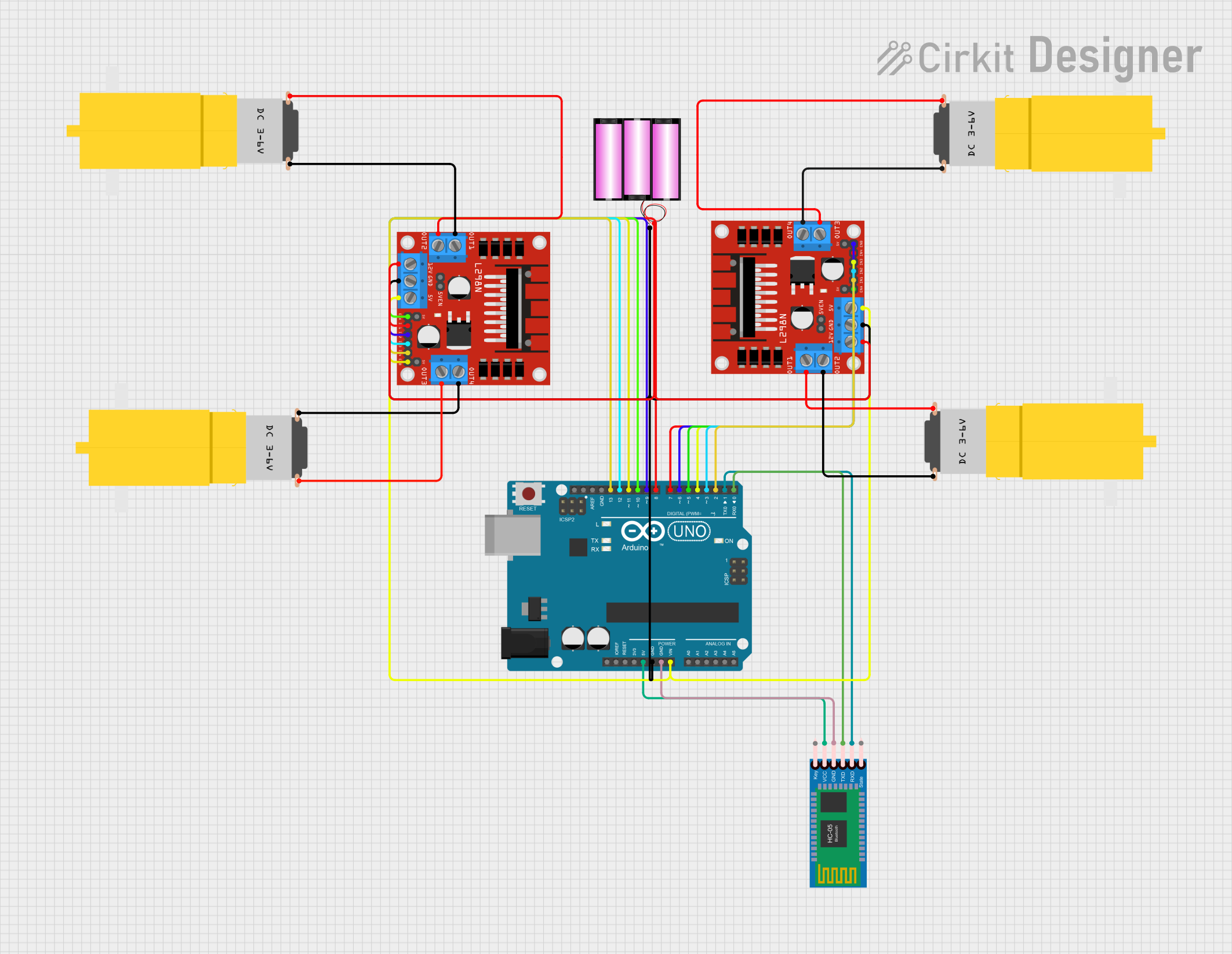
This circuit is designed to control a set of motors using an Arduino UNO microcontroller and L298N DC motor drivers. It includes a Bluetooth module (HC-05) for potential wireless communication. The motors are powered by a 12V battery, which also supplies power to the motor drivers. The Arduino UNO is used to control the motor drivers, which in turn control the speed and direction of the motors.
Component List
Arduino UNO
- Microcontroller board based on the ATmega328P
- It has 14 digital input/output pins, 6 analog inputs, a 16 MHz quartz crystal, a USB connection, a power jack, an ICSP header, and a reset button.
Motor Amarillo Motorreductor Hobby (x4)
- A yellow hobby gear motor
- It operates on a voltage supply and has two pins for power connection (VCC and GND).
Battery 12V
- A 12-volt battery with a positive (+) and negative (-) terminal
- Provides power to the motor drivers and indirectly to the motors.
L298N DC Motor Driver (x2)
- A module capable of driving two DC motors
- It has pins for motor outputs, power supply, logic inputs, and enable pins for controlling motor speed and direction.
HC-05 Bluetooth Module
- A wireless communication module that can be used for serial communication
- It has pins for VCC, GND, TXD, RXD, and STATE.
Wiring Details
Arduino UNO
- 5V connected to HC-05 Bluetooth Module VCC
- GND connected to the negative terminal of the battery, GND of both L298N DC motor drivers, and GND of HC-05 Bluetooth Module
- Vin connected to the 5V pins of both L298N DC motor drivers
- Digital Pins (D0-D13) variously connected to the HC-05 Bluetooth Module and the IN1-IN4 and ENA, ENB pins of both L298N DC motor drivers
Motor Amarillo Motorreductor Hobby
- VCC connected to OUT1 or OUT3 of L298N DC motor drivers
- GND connected to OUT2 or OUT4 of L298N DC motor drivers
Battery 12V
- + connected to the 12V pins of both L298N DC motor drivers
- - connected to the GND pins of both L298N DC motor drivers and Arduino UNO GND
L298N DC Motor Driver
- OUT1, OUT2, OUT3, OUT4 connected to the respective VCC and GND pins of the motors
- 12V connected to the positive terminal of the battery
- GND connected to the negative terminal of the battery and Arduino UNO GND
- 5V connected to Arduino UNO Vin
- IN1-IN4 connected to various digital pins on the Arduino UNO for motor control
- ENA, ENB connected to digital pins on the Arduino UNO for speed control
HC-05 Bluetooth Module
- VCC connected to Arduino UNO 5V
- GND connected to Arduino UNO GND
- TXD connected to Arduino UNO D0
- RXD connected to Arduino UNO D1
Documented Code
Arduino UNO Code (sketch.ino)
void setup() {
  // put your setup code here, to run once:

}

void loop() {
  // put your main code here, to run repeatedly:

}
Note: The provided code is a template and does not include specific functionality. It should be populated with the logic required to control the motors via the L298N motor drivers and to handle communication with the HC-05 Bluetooth module.