ESP32-CAM and GPS-Enabled Robotic Vehicle with Metal Detection
Circuit Documentation
Summary
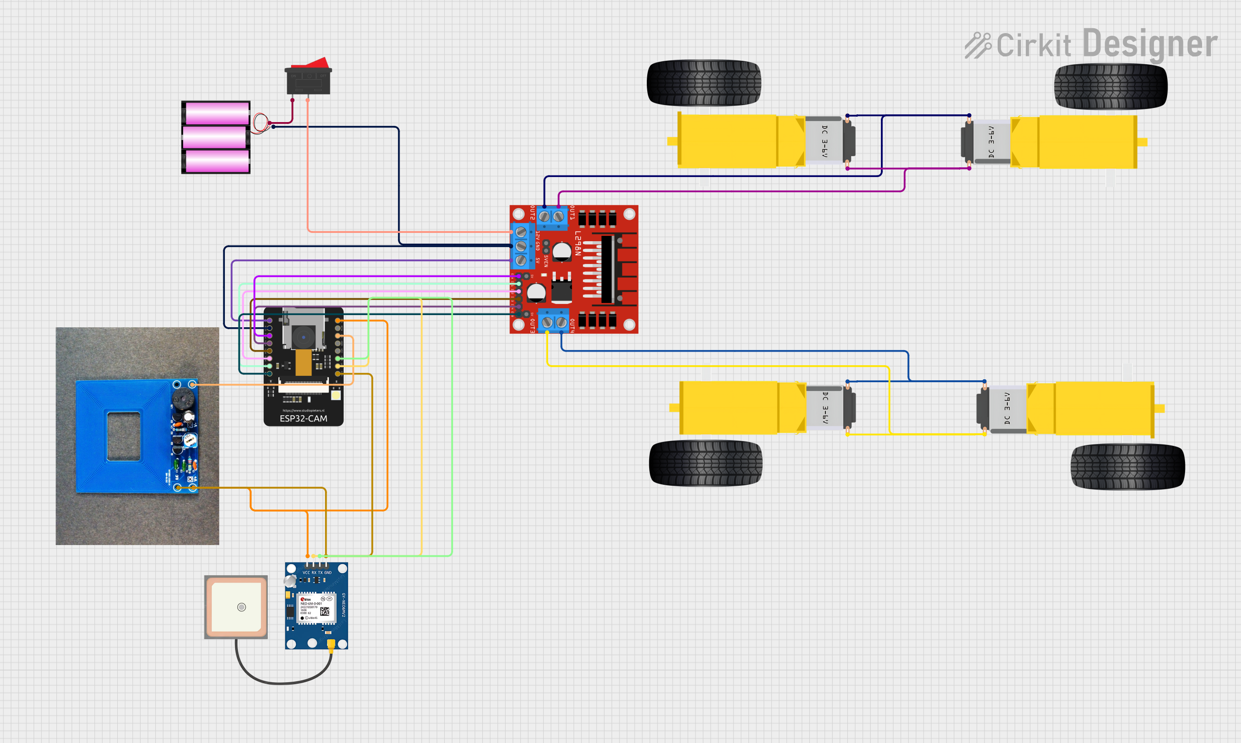
The circuit in question appears to be designed for a mobile platform, possibly a robot or a vehicle, which utilizes a GPS module for positioning, a metal detector for object detection, and an ESP32-CAM for wireless communication and possibly image capture. The circuit is powered by a 12V battery and includes a rocker switch for power control. The L298N motor driver is used to control the gearmotors for the wheels, allowing for bidirectional movement. The ESP32-CAM also interfaces with the GPS module and the metal detector for data processing and decision-making.
Component List
GPS NEO 6M
- Description: GPS module for obtaining geographical position data.
- Pins: VCC, RX, TX, GND
Gearmotor DC Wheels (Right and Left)
- Description: DC gearmotors for driving the wheels of the mobile platform.
- Pins: PIN1, PIN2
Battery 12V
- Description: 12V battery to provide power to the circuit.
- Pins: +, -
Rocker Switch
- Description: A switch to control the power supply to the circuit.
- Pins: 1, 2
L298N DC Motor Driver
- Description: A motor driver module to control the speed and direction of the DC gearmotors.
- Pins: OUT1, OUT2, 12V, GND, 5V, OUT3, OUT4, 5V-ENA-JMP-I, 5V-ENA-JMP-O, +5V-J1, +5V-J2, ENA, IN1, IN2, IN3, IN4, ENB
Metal Detector
- Description: A sensor to detect metallic objects.
- Pins: VCC, GND, D
ESP32 - CAM
- Description: A microcontroller with integrated Wi-Fi and camera support.
- Pins: 5V, GND, IO12, IO13, IO15, IO14, IO2, IO4, VOT, VOR, VCC, IO0, IO16, 3V3
Wiring Details
GPS NEO 6M
- VCC connected to 3V3 of ESP32 - CAM
- RX connected to VOT of ESP32 - CAM
- TX connected to VOR of ESP32 - CAM
- GND connected to GND of ESP32 - CAM
Gearmotor DC Wheels (Right and Left)
- PIN1 and PIN2 of each gearmotor connected to OUT1, OUT2, OUT3, and OUT4 of the L298N motor driver respectively.
Battery 12V
- connected to pin 1 of Rocker Switch
- connected to GND of L298N DC motor driver and GND of ESP32 - CAM
Rocker Switch
- Pin 1 connected to + of battery 12V
- Pin 2 connected to 12V of L298N DC motor driver
L298N DC Motor Driver
- OUT1, OUT2, OUT3, and OUT4 connected to gearmotors
- 12V connected to pin 2 of Rocker Switch
- GND connected to - of battery 12V and GND of ESP32 - CAM
- 5V connected to 5V of ESP32 - CAM
- ENA connected to IO12 of ESP32 - CAM
- IN1 connected to IO2 of ESP32 - CAM
- IN2 connected to IO14 of ESP32 - CAM
- IN3 connected to IO15 of ESP32 - CAM
- IN4 connected to IO13 of ESP32 - CAM
- ENB connected to IO4 of ESP32 - CAM
Metal Detector
- VCC connected to 3V3 of ESP32 - CAM
- GND connected to GND of ESP32 - CAM
- D connected to IO0 of ESP32 - CAM
ESP32 - CAM
- 3V3 connected to VCC of GPS NEO 6M and VCC of Metal Detector
- GND connected to GND of GPS NEO 6M, GND of Metal Detector, and GND of L298N DC motor driver
- IO12 connected to ENA of L298N DC motor driver
- IO2 connected to IN1 of L298N DC motor driver
- IO14 connected to IN2 of L298N DC motor driver
- IO15 connected to IN3 of L298N DC motor driver
- IO13 connected to IN4 of L298N DC motor driver
- IO4 connected to ENB of L298N DC motor driver
- IO0 connected to D of Metal Detector
- 5V connected to 5V of L298N DC motor driver
- VOT connected to RX of GPS NEO 6M
- VOR connected to TX of GPS NEO 6M
Documented Code
No code has been provided for the microcontroller(s) in the circuit. The documentation of the code would typically include a description of the functionality, setup and loop functions, and any functions or libraries used to control the hardware components. Since no code is available, this section cannot be completed.