
Raspberry Pi Pico W UV Monitoring System with OLED Display and RTC
View and Edit Project In Cirkit Designer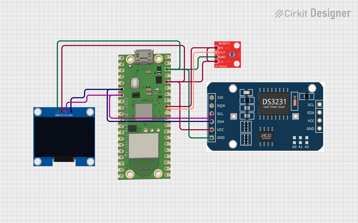
Circuit Documentation
Summary
This document provides a detailed overview of a circuit that includes a Raspberry Pi Pico W microcontroller, a 128x64 OLED Display, an RTC module, and an ML8511 UV Sensor Breakout. The circuit is designed to interface these components for various functionalities such as displaying data on the OLED screen, keeping track of time using the RTC module, and measuring UV light intensity with the UV sensor.
Component List
Raspberry Pi Pico W
- Description: A low-cost, high-performance microcontroller board with flexible digital interfaces.
- Pins: VBUS, VSYS, GP16, GP17, GND, GP18, GP19, GP20, GP21, GP22, RUN, GP26, GP27, GP28, ADC_VREF, 3V3 OUT, 3V3_EN, GP0, GP1, GP2, GP3, GP4, GP5, GP6, GP7, GP15, GP14, GP13, GP12, GP11, GP10, GP9, GP8
128x64 OLED Display (I2C IIC SPI Serial)
- Description: A small, high-contrast display module that uses I2C or SPI for communication.
- Pins: GND, SDA, SCL, VCC
RTC Module
- Description: A real-time clock module for keeping accurate time.
- Pins: 32k, SQW, SCL, SDA, VCC, GND
ML8511 UV Sensor Breakout
- Description: A sensor module for measuring UV light intensity.
- Pins: EN, OUT, GND, 3.3V
Wiring Details
Raspberry Pi Pico W
- GP26 is connected to OUT of the ML8511 UV Sensor Breakout.
- GP27 is connected to 3V3 OUT of the Raspberry Pi Pico W.
- 3V3 OUT is connected to:
- VCC of the 128x64 OLED Display
- VCC of the RTC Module
- EN of the ML8511 UV Sensor Breakout
- 3.3V of the ML8511 UV Sensor Breakout
- GND is connected to:
- GND of the 128x64 OLED Display
- GND of the RTC Module
- GND of the ML8511 UV Sensor Breakout
- GP4 is connected to:
- SDA of the 128x64 OLED Display
- SDA of the RTC Module
- GP5 is connected to:
- SCL of the 128x64 OLED Display
- SCL of the RTC Module
128x64 OLED Display (I2C IIC SPI Serial)
- VCC is connected to 3V3 OUT of the Raspberry Pi Pico W.
- GND is connected to GND of the Raspberry Pi Pico W.
- SDA is connected to GP4 of the Raspberry Pi Pico W.
- SCL is connected to GP5 of the Raspberry Pi Pico W.
RTC Module
- VCC is connected to 3V3 OUT of the Raspberry Pi Pico W.
- GND is connected to GND of the Raspberry Pi Pico W.
- SDA is connected to GP4 of the Raspberry Pi Pico W.
- SCL is connected to GP5 of the Raspberry Pi Pico W.
ML8511 UV Sensor Breakout
- EN is connected to 3V3 OUT of the Raspberry Pi Pico W.
- OUT is connected to GP26 of the Raspberry Pi Pico W.
- GND is connected to GND of the Raspberry Pi Pico W.
- 3.3V is connected to 3V3 OUT of the Raspberry Pi Pico W.
Code
No code is provided for this circuit.
This document provides a comprehensive overview of the circuit, including a summary, a detailed component list, wiring details, and a section for code documentation. This should serve as a useful reference for understanding and replicating the circuit.