Arduino UNO Controlled Security System with Servo Lock and Keypad Interface
Circuit Documentation
Summary
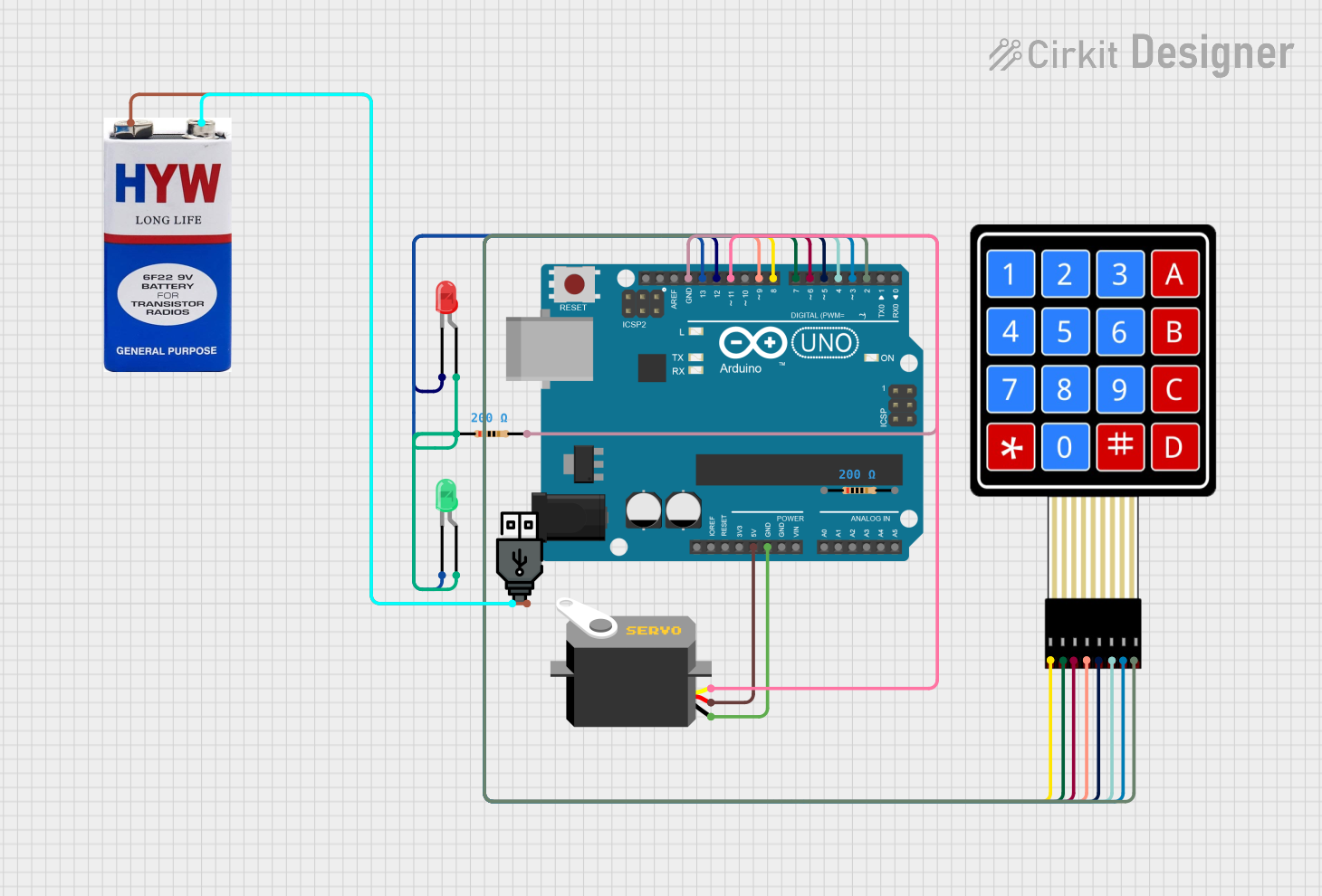
This circuit is designed around an Arduino UNO microcontroller and includes a variety of components to demonstrate a simple security system. The system uses a 4x4 membrane matrix keypad for input, a servo motor as a locking mechanism, and two LEDs (red and green) to indicate the lock status. The Arduino UNO controls the servo based on the input from the keypad and lights up the corresponding LED. The circuit is powered by a USB power source or a 9V battery.
Component List
Arduino UNO
- Microcontroller board based on the ATmega328P
- It has 14 digital input/output pins, 6 analog inputs, a 16 MHz quartz crystal, a USB connection, a power jack, an ICSP header, and a reset button.
LED: Two Pin (red)
- A red light-emitting diode (LED) with an anode and cathode pin.
LED: Two Pin (green)
- A green light-emitting diode (LED) with an anode and cathode pin.
Servo
- A small device that has an output shaft. This shaft can be positioned to specific angular positions by sending the servo a coded signal.
4X4 Membrane Matrix Keypad
- A 16-button keypad that provides a useful human interface component for microcontroller projects.
Resistor (200 Ohms)
- A resistor with a resistance of 200 Ohms, used to limit current to the LEDs.
9V Battery
- A standard 9V battery used to provide power to the circuit.
USB Power
- A USB power source that can be used to power the circuit.
Wiring Details
Arduino UNO
5VandGNDare used to power the Servo.- Digital pins
D2toD9are connected to the 4x4 membrane matrix keypad. - Digital pins
D11,D12, andD13are used to control the Servo and LEDs.
LED: Two Pin (red)
Cathodeconnected to Arduino UNO pinD12.Anodeconnected to a 200 Ohm resistor.
LED: Two Pin (green)
Cathodeconnected to Arduino UNO pinD13.Anodeconnected to the same 200 Ohm resistor as the red LED.
Servo
GNDconnected to Arduino UNOGND.VCCconnected to Arduino UNO5V.Pulseconnected to Arduino UNO pinD11.
4X4 Membrane Matrix Keypad
R1toR4connected to Arduino UNO pinsD8toD9.C1toC4connected to Arduino UNO pinsD5toD2.
Resistor (200 Ohms)
- One side connected to the anodes of both the red and green LEDs.
- The other side connected to Arduino UNO
GND.
9V Battery and USB Power
+of both power sources are connected together.-of both power sources are connected together.
Documented Code
Arduino UNO Code (sketch.ino)
#include <Servo.h>
#include <Keypad.h>

Servo ServoMotor;
char* password = "427";  // change the password here, just pick any 3 numbers
int position = 0;
const byte ROWS = 4;
const byte COLS = 4;
char keys[ROWS][COLS]  = {
  {'1','2','3','A'},
  {'4','5','6','B'},
  {'7','8','9','C'},
  {'*','0','#','D'}
};

byte rowPins[ROWS] = { 8, 7, 6, 9 };
byte colPins[COLS] = { 5, 4, 3, 2 };
Keypad keypad = Keypad( makeKeymap(keys), rowPins, colPins, ROWS, COLS );
int RedpinLock  = 12;
int GreenpinUnlock = 13;

void setup()
{
  pinMode(RedpinLock,  OUTPUT);
  pinMode(GreenpinUnlock, OUTPUT);
  ServoMotor.attach(11);
  LockedPosition(true);
}

void loop()
{
  char key = keypad.getKey();
  if (key == '*' || key == '#')
  {
    position  = 0;
    LockedPosition(true);
  }
  if (key == password[position])
  {
    position  ++;
  }
  if (position == 3)
  {
    LockedPosition(false);
  }
  delay(100);
}

void LockedPosition(int locked)
{
  if (locked)
  {
    digitalWrite(RedpinLock,  HIGH);
    digitalWrite(GreenpinUnlock, LOW);
    ServoMotor.write(11);
  }
  else
  {
    digitalWrite(RedpinLock,  LOW);
    digitalWrite(GreenpinUnlock, HIGH);
    ServoMotor.write(90);
  }
}
This code is responsible for controlling the servo motor based on the input from the keypad. It also controls the red and green LEDs to indicate the lock status. When the correct password is entered, the green LED lights up, and the servo moves to the unlock position. If an incorrect key is pressed, the red LED lights up, and the servo remains in the locked position.