Cirkit Designer
Your all-in-one circuit design IDE
Home /
Project Documentation
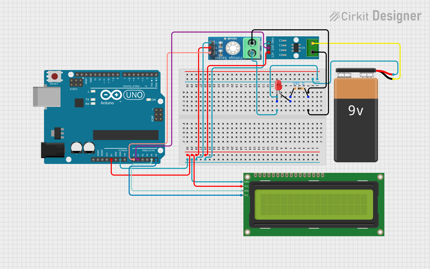
Arduino UNO Power Meter with I2C LCD Display and Current/Voltage Sensors
Circuit Documentation
Summary
This circuit is designed to measure voltage, current, and power using an Arduino UNO, a 16x2 I2C LCD, a voltage sensor, and a current sensor. The measured values are displayed on the LCD and can also be monitored via the Arduino's serial monitor.
Component List
16x2 I2C LCD
- Pins: GND, VCC, SDA, SCL
- Description: A 16x2 character LCD display with I2C interface.
- Purpose: To display voltage, current, and power measurements.
LED: Two Pin (red)
- Pins: cathode, anode
- Description: A standard red LED.
- Purpose: Visual indicator.
Resistor
- Pins: pin1, pin2
- Description: A resistor with a resistance of 390 Ohms.
- Purpose: Current limiting for the LED.
9V Battery
- Pins: -, +
- Description: A 9V battery.
- Purpose: Power supply for the circuit.
ACS712 Current Sensor 5A 20A 30A
- Pins: 1, 2, GND, OUT, VCC
- Description: A current sensor capable of measuring up to 30A.
- Purpose: To measure the current flowing through the circuit.
Voltage Sensor DC 25V
- Pins: +, -, output, gnd, vcc
- Description: A voltage sensor capable of measuring up to 25V.
- Purpose: To measure the voltage in the circuit.
Arduino UNO
- Pins: UNUSED, IOREF, Reset, 3.3V, 5V, GND, Vin, A0, A1, A2, A3, A4, A5, SCL, SDA, AREF, D13, D12, D11, D10, D9, D8, D7, D6, D5, D4, D3, D2, D1, D0
- Description: A microcontroller board based on the ATmega328P.
- Purpose: To process sensor data and control the LCD display.
Wiring Details
16x2 I2C LCD
- GND connected to GND of Arduino UNO
- VCC connected to 5V of Arduino UNO
- SDA connected to A4 of Arduino UNO
- SCL connected to A5 of Arduino UNO
LED: Two Pin (red)
- cathode connected to gnd of Voltage Sensor DC 25V
- anode connected to pin1 of Resistor
Resistor
- pin1 connected to anode of LED
- pin2 connected to vcc of Voltage Sensor DC 25V and 1 of ACS712 Current Sensor
9V Battery
- - connected to 2 of ACS712 Current Sensor
- + connected to gnd of Voltage Sensor DC 25V and cathode of LED
ACS712 Current Sensor 5A 20A 30A
- 1 connected to pin2 of Resistor
- 2 connected to - of 9V Battery
- GND connected to - of Voltage Sensor DC 25V and GND of Arduino UNO
- OUT connected to A1 of Arduino UNO
- VCC connected to + of Voltage Sensor DC 25V and 5V of Arduino UNO
Voltage Sensor DC 25V
- + connected to VCC of ACS712 Current Sensor and 5V of Arduino UNO
- - connected to GND of ACS712 Current Sensor and GND of Arduino UNO
- output connected to A0 of Arduino UNO
- gnd connected to cathode of LED and + of 9V Battery
- vcc connected to pin2 of Resistor and 1 of ACS712 Current Sensor
Arduino UNO
- 5V connected to VCC of 16x2 I2C LCD, VCC of ACS712 Current Sensor, and + of Voltage Sensor DC 25V
- GND connected to GND of 16x2 I2C LCD, GND of ACS712 Current Sensor, and - of Voltage Sensor DC 25V
- A0 connected to output of Voltage Sensor DC 25V
- A1 connected to OUT of ACS712 Current Sensor
- A4 connected to SDA of 16x2 I2C LCD
- A5 connected to SCL of 16x2 I2C LCD
Code Documentation
#include <Wire.h>
#include <LiquidCrystal_I2C.h>

// I2C LCD Initialization
LiquidCrystal_I2C lcd(0x27, 16, 2);

// Sensor Pins
const int VOLTAGE_SENSOR = A0;
const int CURRENT_SENSOR = A1;

// Calibration values
const float VOLTAGE_FACTOR = 5.0 / 1024.0; // 5V reference / 1024 steps
const float VOLTAGE_DIVIDER_RATIO = 4.964;  // HW-067
const float CURRENT_SENSITIVITY = 1.33985;    // Sensitivity for ACS712 5A
const float VOLTAGE_OFFSET = 2.5;
const int SAMPLES = 100;                    // Number of samples for averaging
const float CURRENT_THRESHOLD = 0.013;     // Ignore readings below 13mA

// Function to get average reading from a pin
float getAverageReading(int pin) {
  long sum = 0;
  for(int i = 0; i < SAMPLES; i++) {
    sum += analogRead(pin);
    delayMicroseconds(100);
  }
  return sum / (float)SAMPLES;
}

void setup() {
  Serial.begin(9600);
  lcd.init();
  lcd.backlight();

  pinMode(VOLTAGE_SENSOR, INPUT);
  pinMode(CURRENT_SENSOR, INPUT);

  delay(120);

  lcd.clear();
  lcd.setCursor(0, 0);
  lcd.print("Guc Olcer Hazir");
  delay(2500);
}

void loop() {
  // Get readings
  float rawVoltage = getAverageReading(VOLTAGE_SENSOR);
  float rawCurrent = getAverageReading(CURRENT_SENSOR);

  // Calculate voltage
  float voltage = (rawVoltage * VOLTAGE_FACTOR * VOLTAGE_DIVIDER_RATIO);

  // Calculate current
  float voltage_current = (rawCurrent * VOLTAGE_FACTOR);
  float current = ((voltage_current - VOLTAGE_OFFSET) / CURRENT_SENSITIVITY);

  // Apply current threshold
  current = abs(current);
  if(current < CURRENT_THRESHOLD) {
    current = 0;
  }

  // Calculate power
  float power = voltage * current;

  // Convert to mA and mW
  float current_mA = current * 1000;
  float power_mW = power * 1000;

  // Ensure power is zero if current is zero
  if(current == 0) {
    power_mW = 0;
  }

  // Display on LCD
  lcd.clear();
  lcd.setCursor(0, 0);
  lcd.print("V:");
  lcd.print(voltage, 1);
  lcd.print("V I:");
  lcd.print(current_mA, 1);
  lcd.print("mA");

  lcd.setCursor(0, 1);
  lcd.print("Guc:");
  lcd.print(power_mW, 1);
  lcd.print("mW");

  // Print to Serial Monitor
  Serial.println("Olcumler:");
  Serial.print("Voltaj: ");
  Serial.print(voltage, 3);
  Serial.println("V");

  Serial.print("Akim: ");
  Serial.print(current_mA, 3);
  Serial.println("mA");

  Serial.print("Guc: ");
  Serial.print(power_mW, 3);
  Serial.println("mW");
  Serial.println();

  delay(500);
}
This code initializes the I2C LCD and sets up the voltage and current sensors. It reads the sensor values, calculates the voltage, current, and power, and displays these values on the LCD and the serial monitor.