
Arduino-Controlled Robotics Interface with Servo and Stepper Motors
View and Edit Project In Cirkit Designer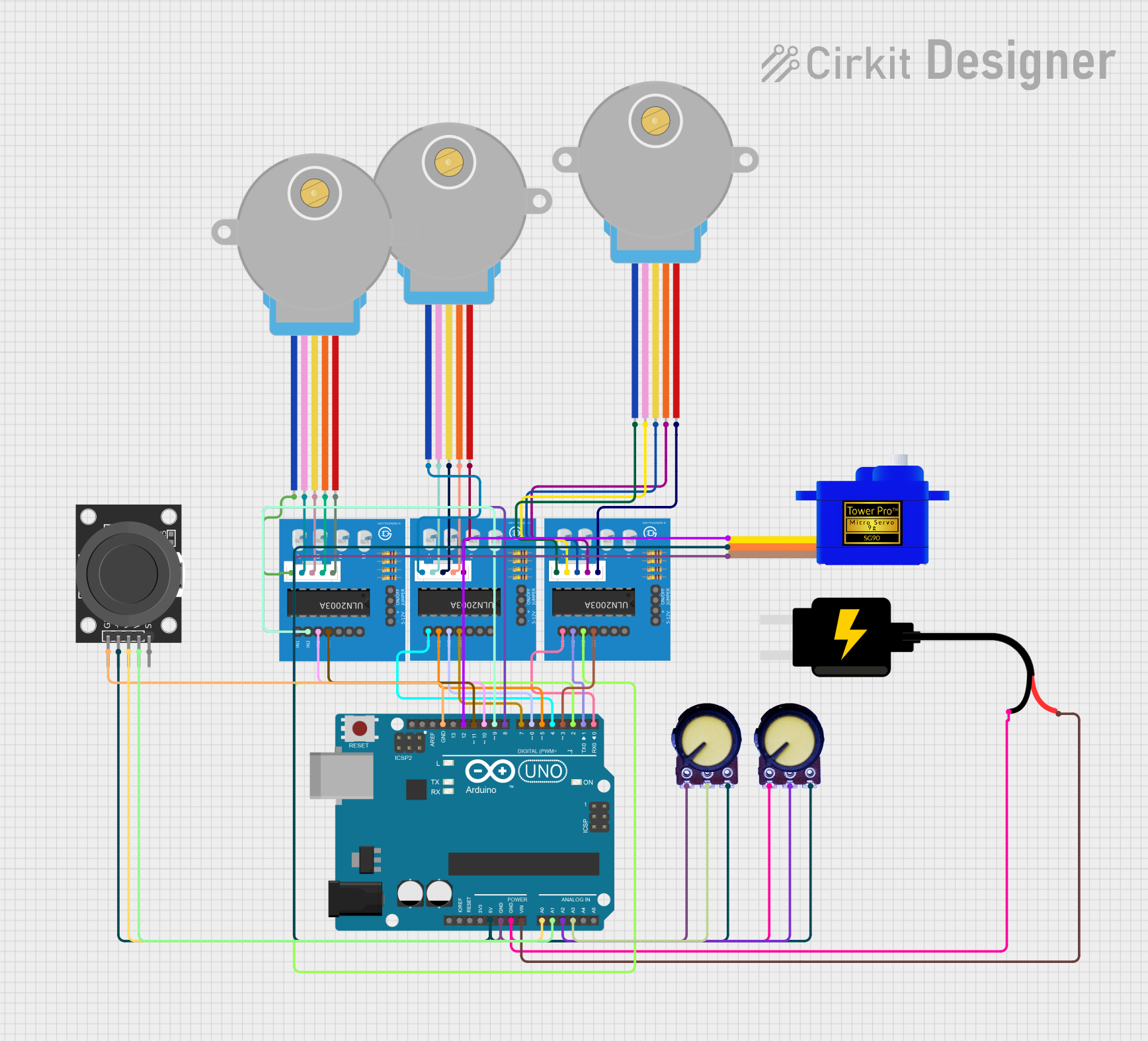
Circuit Documentation
Summary
This circuit is designed around an Arduino UNO microcontroller and includes various components such as potentiometers, a dual-axis joystick module, a servomotor, stepper motors, and ULN2003A breakout boards to drive the stepper motors. The circuit is powered by a 5V DC source, and the Arduino UNO is used to control the servomotor and stepper motors based on inputs from the potentiometers and the joystick module.
Component List
Arduino UNO
- Microcontroller board based on the ATmega328P
- It has 14 digital input/output pins, 6 analog inputs, a 16 MHz quartz crystal, a USB connection, a power jack, an ICSP header, and a reset button.
ULN2003A Breakout Board
- A breakout board for the ULN2003A Darlington transistor array
- It is used to drive stepper motors with higher current requirements.
28BYJ-48 Stepper Motor
- A small, 5-line, 4-phase stepper motor
- It can be driven by ULN2003A breakout boards.
Servomotor SG90
- A small and lightweight servo motor
- Capable of precise control.
KY-023 Dual Axis Joystick Module
- A joystick module with two axes and a pushbutton switch
- Provides analog input to the Arduino UNO.
DC Source 5V
- Provides a 5V power supply to the circuit.
Potentiometer
- A variable resistor with three terminals
- Provides analog input to the Arduino UNO.
Wiring Details
Arduino UNO
- 5V connected to Potentiometers (VCC), Servomotor SG90 (VCC), KY-023 Joystick Module (+5V)
- GND connected to Servomotor SG90 (GND), Potentiometers (GND), KY-023 Joystick Module (GND), DC Source 5V (GND)
- Vin connected to DC Source 5V (VCC)
- A0 connected to KY-023 Joystick Module (VRx)
- A1 connected to KY-023 Joystick Module (VRy)
- A2 connected to Potentiometer (Output)
- A3 connected to Potentiometer (Output)
- D0-D12 connected to ULN2003A Breakout Boards (In 1-In 4) and Servomotor SG90 (SIG)
ULN2003A Breakout Board
- In 1-In 7 connected to corresponding Arduino UNO digital pins
- 0V connected to Arduino UNO GND
- +5V connected to Arduino UNO 5V
- BLUE, PINK, YELLOW, ORANGE, RED wires connected to corresponding wires of 28BYJ-48 Stepper Motors
28BYJ-48 Stepper Motor
- BLUE, PINK, YELLOW, ORANGE, RED connected to corresponding wires on ULN2003A Breakout Boards
Servomotor SG90
- SIG connected to Arduino UNO D12
- VCC connected to Arduino UNO 5V
- GND connected to Arduino UNO GND
KY-023 Dual Axis Joystick Module
- GND connected to Arduino UNO GND
- +5V connected to Arduino UNO 5V
- VRx connected to Arduino UNO A0
- VRy connected to Arduino UNO A1
- SW not connected in this circuit
DC Source 5V
- VCC connected to Arduino UNO Vin
- GND connected to Arduino UNO GND
Potentiometer
- GND connected to Arduino UNO GND
- Output connected to Arduino UNO A2 or A3
- VCC connected to Arduino UNO 5V
Documented Code
Arduino UNO Code (sketch.ino)
void setup() {
  // put your setup code here, to run once:

}

void loop() {
  // put your main code here, to run repeatedly:

}
Note: The provided code is a template and does not include specific functionality. It needs to be completed with the logic to read inputs from the joystick and potentiometers and to control the servomotor and stepper motors accordingly.