Arduino-Controlled Robotic Vehicle with Ultrasonic Obstacle Detection and Joystick Navigation
Circuit Documentation
Summary of the Circuit
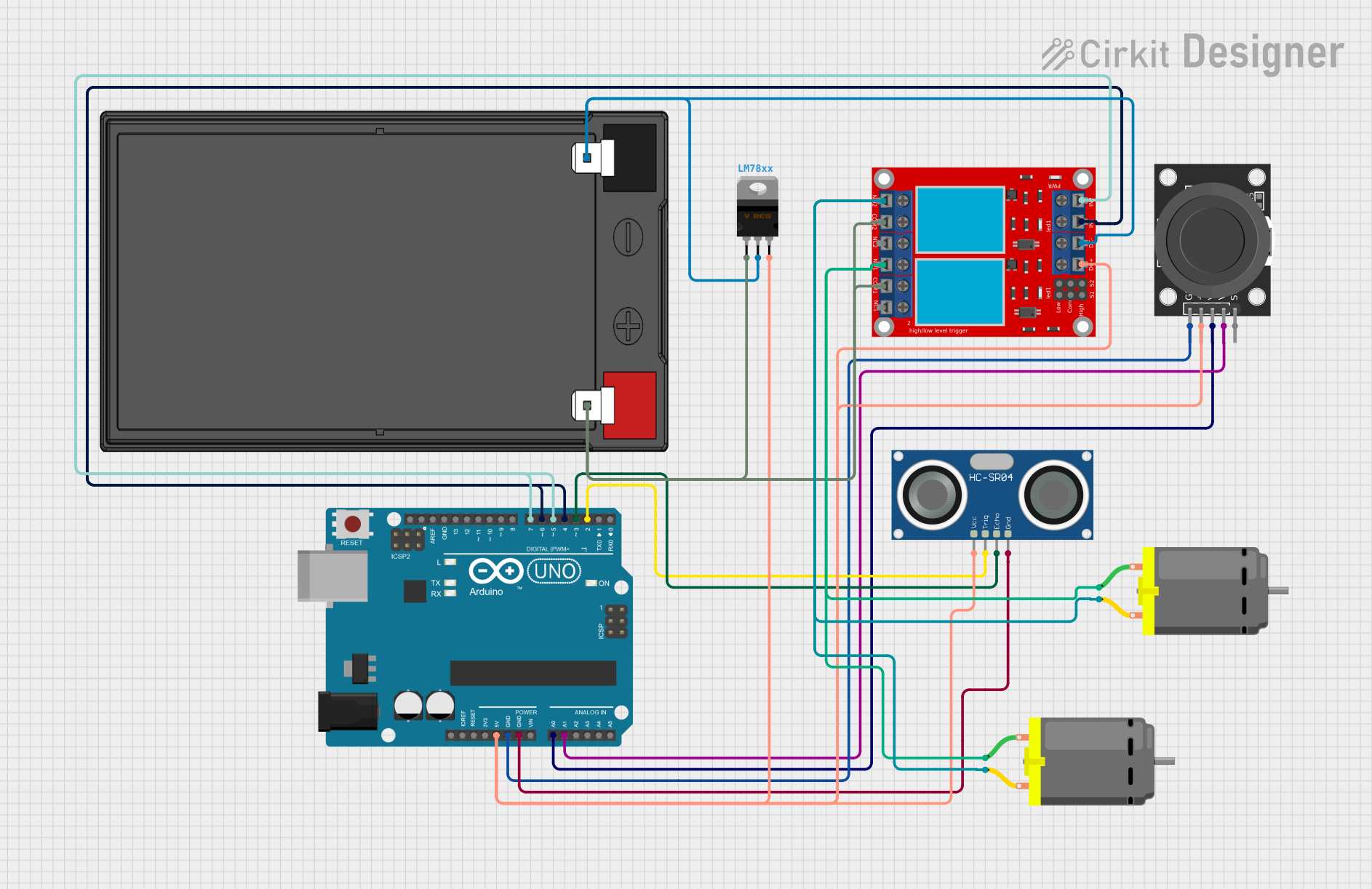
This circuit is designed to control a pair of DC motors using an Arduino UNO microcontroller in conjunction with a 2-channel relay module. The control input is provided by a KY-023 Dual Axis Joystick Module. An HC-SR04 Ultrasonic Sensor is included for distance measurement, which can be used for obstacle detection or distance-based control logic. The circuit is powered by a 12V 7Ah battery, and a LM78xx Voltage Regulator is used to step down the voltage to 5V required by the Arduino UNO and other 5V components.
Component List
DC Motor
- Description: Electric motor that converts DC electrical power into mechanical rotation.
- Purpose: To provide motion to the system, controlled by the relay module.
HC-SR04 Ultrasonic Sensor
- Description: A sensor that measures distance by emitting ultrasonic waves and measuring the time taken for the echo to return.
- Purpose: To detect obstacles or measure the distance from an object.
LM78xx Voltage Regulator
- Description: A voltage regulator that outputs a stable 5V from a higher voltage input.
- Purpose: To provide a regulated 5V supply to the 5V components in the circuit.
KY-023 Dual Axis Joystick Module
- Description: A module that provides two analog outputs corresponding to the X and Y positions of the joystick.
- Purpose: To serve as a user input device for controlling the motion of the DC motors.
Arduino UNO
- Description: A microcontroller board based on the ATmega328P, with digital and analog I/O pins.
- Purpose: To process input signals and control other components in the circuit.
12v 7ah Battery
- Description: A rechargeable battery providing a 12V output.
- Purpose: To supply power to the circuit.
2 Channel Relay Module
- Description: A module with two independent relays that can control high power devices.
- Purpose: To switch the DC motors on and off, allowing for motor control by the Arduino.
Wiring Details
DC Motor
- Wiring:
pin 1of both motors connected toN.O. 1andN.O. 2on the relay module.pin 2of both motors connected toN.O. 2on the relay module.
HC-SR04 Ultrasonic Sensor
- Wiring:
VCCconnected to5Von the Arduino UNO.GNDconnected toGNDon the Arduino UNO.TRIGconnected toD2on the Arduino UNO.ECHOconnected toD3on the Arduino UNO.
LM78xx Voltage Regulator
- Wiring:
Inputconnected to12v +on the battery.GNDconnected to12v -on the battery.Outputproviding5Vto the Arduino UNO and other 5V components.
KY-023 Dual Axis Joystick Module
- Wiring:
GNDconnected toGNDon the Arduino UNO.+5Vconnected to5Von the Arduino UNO.VRxconnected toA0on the Arduino UNO.VRyconnected toA1on the Arduino UNO.
Arduino UNO
- Wiring:
5VandGNDpins used to distribute power to other 5V components.- Analog pins
A0andA1connected to the joystick module. - Digital pins
D2andD3connected to the ultrasonic sensor. - Digital pins
D4,D5,D6, andD7connected to the relay module inputs.
12v 7ah Battery
- Wiring:
12v +connected to the voltage regulator input andCOM 1andCOM 2on the relay module.12v -connected to the voltage regulator ground andVCC- (GND)on the relay module.
2 Channel Relay Module
- Wiring:
VCC+connected to5Von the Arduino UNO.VCC- (GND)connected toGNDon the Arduino UNO.IN 1andIN 2controlled by digital pinsD4,D5,D6, andD7on the Arduino UNO.
Documented Code
Code for Arduino UNO
// Define pins for joystick
const int joystickX = A0;    // Analog pin for joystick X-axis
const int joystickY = A1;    // Analog pin for joystick Y-axis

// Define pins for relay module
const int relayPin1 = 5;     // Relay pin 1 (controls Motor 1)
const int relayPin2 = 6;     // Relay pin 2 (controls Motor 2)

void setup() {
  // Initialize joystick pins as input
  pinMode(joystickX, INPUT);
  pinMode(joystickY, INPUT);

  // Initialize relay pins as output
  pinMode(relayPin1, OUTPUT);
  pinMode(relayPin2, OUTPUT);
}

void loop() {
  int xValue = analogRead(joystickX); // Read joystick X value
  int yValue = analogRead(joystickY); // Read joystick Y value

  // Map the joystick values to motor control logic
  if (yValue < 400) {
    // Move forward
    digitalWrite(relayPin1, HIGH);
    digitalWrite(relayPin2, HIGH);
  } else if (yValue > 600) {
    // Move backward
    digitalWrite(relayPin1, LOW);
    digitalWrite(relayPin2, LOW);
  } else if (xValue < 400) {
    // Turn left
    digitalWrite(relayPin1, LOW);
    digitalWrite(relayPin2, HIGH);
  } else if (xValue > 600) {
    // Turn right
    digitalWrite(relayPin1, HIGH);
    digitalWrite(relayPin2, LOW);
  } else {
    // Stop
    digitalWrite(relayPin1, LOW);
    digitalWrite(relayPin2, LOW);
  }

  delay(100); // Delay for stability
}
This code snippet is responsible for reading the joystick's analog values and mapping them to control the DC motors via the relay module. The joystick's Y-axis controls forward and backward motion, while the X-axis controls left and right turns. The motors are stopped when the joystick is in the neutral position.