ESP8266-Controlled Load Cell and Ultrasonic Sensor System
Circuit Documentation
Summary
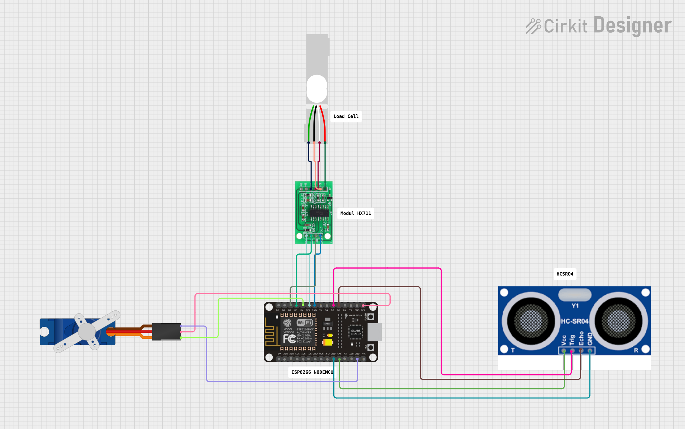
The circuit in question is designed to interface a load cell with an HX711 bridge sensor interface, which is then connected to an ESP8266 NodeMCU microcontroller. The microcontroller also interfaces with an HC-SR04 ultrasonic sensor and controls a Tower Pro SG90 servo motor. The load cell measures weight, the HX711 processes the signal, the ultrasonic sensor measures distance, and the servo motor can be positioned accordingly. The ESP8266 NodeMCU serves as the central processing unit, reading data from the sensors and controlling the servo based on the programmed logic.
Component List
HX711 - Bridge Sensor Interface
- Description: A precision 24-bit analog-to-digital converter (ADC) designed for weigh scales and industrial control applications to interface directly with a bridge sensor.
- Pins: E+, E-, A-, A+, B-, B+, GND, DATA (OUT), SCK (CLOCK IN), 3.3/3.5V Supply
Load Cell - Red/white/black/green
- Description: A transducer that generates an electrical signal whose magnitude is directly proportional to the force being measured.
- Pins: E+, A-, E-, A+
ESP8266 NodeMCU
- Description: A low-cost Wi-Fi microchip with full TCP/IP stack and microcontroller capability.
- Pins: D0, D1, D2, D3, D4, 3V3, GND, D5, D6, D7, D8, RX, TX, A0, RSV, SD3, SD2, SD1, CMD, SD0, CLK, EN, RST, VIN
Ultrasonic Sensor HC-SR04
- Description: An ultrasonic ranging module that provides 2cm to 400cm non-contact measurement functionality.
- Pins: GND, ECHO, TRIG, VCC
Tower Pro SG90 Servo
- Description: A small and lightweight servo motor capable of precise control.
- Pins: Signal, +5V, GND
Wiring Details
HX711 - Bridge Sensor Interface
- E+ connected to Load Cell E+
- E- connected to Load Cell E-
- A- connected to Load Cell A-
- A+ connected to Load Cell A+
- GND connected to ESP8266 NodeMCU GND
- DATA (OUT) connected to ESP8266 NodeMCU D2
- SCK (CLOCK IN) connected to ESP8266 NodeMCU D3
- 3.3/3.5V Supply connected to ESP8266 NodeMCU 3V3
Load Cell - Red/white/black/green
- E+ connected to HX711 E+
- A- connected to HX711 A-
- E- connected to HX711 E-
- A+ connected to HX711 A+
ESP8266 NodeMCU
- GND connected to HX711 GND, Ultrasonic Sensor GND, and Tower Pro SG90 Servo GND
- D2 connected to HX711 DATA (OUT)
- D3 connected to HX711 SCK (CLOCK IN)
- D4 connected to Tower Pro SG90 Servo Signal
- D7 connected to Ultrasonic Sensor TRIG
- D8 connected to Ultrasonic Sensor ECHO
- 3V3 connected to HX711 3.3/3.5V Supply, Ultrasonic Sensor VCC, and Tower Pro SG90 Servo +5V
Ultrasonic Sensor HC-SR04
- GND connected to ESP8266 NodeMCU GND
- ECHO connected to ESP8266 NodeMCU D8
- TRIG connected to ESP8266 NodeMCU D7
- VCC connected to ESP8266 NodeMCU 3V3
Tower Pro SG90 Servo
- Signal connected to ESP8266 NodeMCU D4
- +5V connected to ESP8266 NodeMCU 3V3
- GND connected to ESP8266 NodeMCU GND
Documented Code
No code has been provided for the microcontrollers in the circuit. The documentation of the code would typically include a description of the functionality, setup, and main loop, along with any functions or libraries used. Since no code is available, this section cannot be completed. If code becomes available, it should be added here with appropriate comments and explanations.