
Raspberry Pi 4B Smart Door Lock System with Fingerprint and Keypad Authentication
View and Edit Project In Cirkit Designer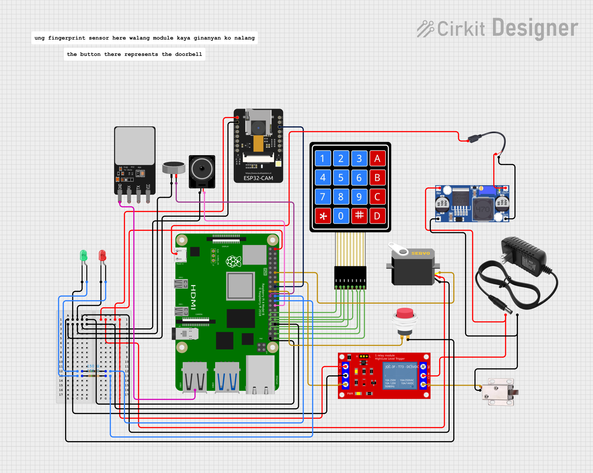
Circuit Documentation
Summary
This circuit is a comprehensive security system that integrates various components such as a Raspberry Pi 4B, ESP32-CAM, fingerprint scanner, membrane keypad, servo motor, relay module, LEDs, loudspeaker, condenser microphone, and a solenoid lock. The system is designed to provide multiple methods of authentication (keypad, fingerprint) and includes features like video streaming, image capture, and doorbell functionality.
Component List
Raspberry Pi 4B
- Description: Main microcontroller for the system.
- Pins: 3V3, 5V, GPIO2, GPIO3, GND, GPIO4, GPIO14, GPIO15, GPIO17, GPIO18, GPIO27, GPIO22, GPIO23, GPIO24, GPIO10, GPIO9, GPIO25, GPIO11, GPIO8, GPIO7, ID_SD, GPIO5, GPIO6, GPIO12, GPIO13, GPIO19, GPIO16, GPIO26, GPIO20, GPIO21, ID_SC, TR01_TAP, TR00_TAP, TR03_TAP, TR02_TAP, RUN, GLOBAL_EN
4X4 Membrane Matrix Keypad
- Description: Used for keypad-based authentication.
- Pins: R1, R2, R3, R4, C1, C2, C3, C4
Servo
- Description: Controls the locking mechanism.
- Pins: gnd, vcc, pulse
1 Channel 5V Relay Module
- Description: Controls the solenoid lock.
- Pins: VCC+, VCC- (GND), IN, N.O., COM, N.C.
12V Power Supply
- Description: Provides power to the circuit.
- Pins: +, -
ESP32-CAM
- Description: Used for video streaming and image capture.
- Pins: 5V, GND, IO12, IO13, IO15, IO14, IO2, IO4, VOT, VOR, VCC, IO0, IO16, 3V3
Fingerprint Scanner
- Description: Used for fingerprint-based authentication.
- Pins: VCC, TX, RX, GND
LED: Two Pin (red)
- Description: Indicates the status of the system.
- Pins: cathode, anode
LED: Two Pin (green)
- Description: Indicates the status of the system.
- Pins: cathode, anode
Loudspeaker
- Description: Provides audio feedback.
- Pins: pin1, pin2
Condenser Microphone
- Description: Captures audio.
- Pins: pin1, pin2
2Pin Push Switch
- Description: Used as a doorbell.
- Pins: Input +, Output +
12V Solenoid Lock
- Description: Controls the door locking mechanism.
- Pins: VCC, GND
Buck Converter
- Description: Converts 12V to 5V.
- Pins: IN+, IN-, OUT+, OUT-
Micro USB to Cable (2 Pin)
- Description: Provides power to the Raspberry Pi.
- Pins: Micro USB, +, -
Resistor (150 Ohms)
- Description: Current limiting resistor for LEDs.
- Pins: pin1, pin2
Wiring Details
Raspberry Pi 4B
- 5V: Connected to 5V pin of ESP32-CAM, Servo (vcc), and Relay Module (VCC+).
- GND: Connected to GND pin of ESP32-CAM, Servo (gnd), Loudspeaker (pin1), Condenser Microphone (pin1), and Relay Module (VCC- (GND)).
- GPIO25: Connected to pin2 of Resistor (150 Ohms) which is connected to the anode of the red LED.
- GPIO8: Connected to pin2 of Resistor (150 Ohms) which is connected to the anode of the green LED.
- GPIO18: Connected to pulse pin of Servo.
- GPIO23: Connected to IN pin of Relay Module.
- GPIO24: Connected to IO0 pin of ESP32-CAM.
- GPIO10: Connected to Input + pin of 2Pin Push Switch.
- GPIO9: Connected to pin2 of Condenser Microphone.
- GPIO7: Connected to pin2 of Loudspeaker.
- GPIO5: Connected to R1 pin of 4X4 Membrane Matrix Keypad.
- GPIO6: Connected to R2 pin of 4X4 Membrane Matrix Keypad.
- GPIO12: Connected to C1 pin of 4X4 Membrane Matrix Keypad.
- GPIO13: Connected to R3 pin of 4X4 Membrane Matrix Keypad.
- GPIO19: Connected to R4 pin of 4X4 Membrane Matrix Keypad.
- GPIO16: Connected to C2 pin of 4X4 Membrane Matrix Keypad.
- GPIO20: Connected to C3 pin of 4X4 Membrane Matrix Keypad.
- GPIO21: Connected to C4 pin of 4X4 Membrane Matrix Keypad.
4X4 Membrane Matrix Keypad
- R1: Connected to GPIO5 of Raspberry Pi.
- R2: Connected to GPIO6 of Raspberry Pi.
- R3: Connected to GPIO13 of Raspberry Pi.
- R4: Connected to GPIO19 of Raspberry Pi.
- C1: Connected to GPIO12 of Raspberry Pi.
- C2: Connected to GPIO16 of Raspberry Pi.
- C3: Connected to GPIO20 of Raspberry Pi.
- C4: Connected to GPIO21 of Raspberry Pi.
Servo
- gnd: Connected to GND of Raspberry Pi.
- vcc: Connected to 5V of Raspberry Pi.
- pulse: Connected to GPIO18 of Raspberry Pi.
1 Channel 5V Relay Module
- VCC+: Connected to 5V of Raspberry Pi.
- VCC- (GND): Connected to GND of Raspberry Pi.
- IN: Connected to GPIO23 of Raspberry Pi.
- N.O.: Connected to VCC of 12V solenoid lock.
- COM: Connected to IN+ of Buck converter and + of 12V power supply.
12V Power Supply
- +: Connected to IN+ of Buck converter and COM of Relay Module.
- -: Connected to IN- of Buck converter and GND of 12V solenoid lock.
ESP32-CAM
- 5V: Connected to 5V of Raspberry Pi.
- GND: Connected to GND of Raspberry Pi.
- IO0: Connected to GPIO24 of Raspberry Pi.
Fingerprint Scanner
- GND: Connected to GND of Raspberry Pi.
LED: Two Pin (red)
- cathode: Connected to GND of Raspberry Pi.
- anode: Connected to pin1 of Resistor (150 Ohms).
LED: Two Pin (green)
- cathode: Connected to GND of Raspberry Pi.
- anode: Connected to pin1 of Resistor (150 Ohms).
Loudspeaker
- pin1: Connected to GND of Raspberry Pi.
- pin2: Connected to GPIO7 of Raspberry Pi.
Condenser Microphone
- pin1: Connected to GND of Raspberry Pi.
- pin2: Connected to GPIO9 of Raspberry Pi.
2Pin Push Switch
- Input +: Connected to GPIO10 of Raspberry Pi.
- Output +: Connected to GND of Raspberry Pi.
12V Solenoid Lock
- VCC: Connected to N.O. of Relay Module.
- GND: Connected to GND of 12V power supply.
Buck Converter
- IN+: Connected to + of 12V power supply.
- IN-: Connected to - of 12V power supply.
- OUT+: Connected to + of Micro USB to Cable.
- OUT-: Connected to - of Micro USB to Cable.
Micro USB to Cable (2 Pin)
- Micro USB: Connected to Raspberry Pi.
- +: Connected to OUT+ of Buck converter.
- -: Connected to OUT- of Buck converter.
Resistor (150 Ohms)
- pin1: Connected to anode of red LED.
- pin2: Connected to GPIO25 of Raspberry Pi.
Resistor (150 Ohms)
- pin1: Connected to anode of green LED.
- pin2: Connected to GPIO8 of Raspberry Pi.
Code Documentation
import RPi.GPIO as GPIO
import time
from pyfingerprint.pyfingerprint import PyFingerprint
from picamera import PiCamera
import os
import serial

# GPIO setup