
Arduino UNO-Based Smart Security System with RFID and Ultrasonic Sensors
View and Edit Project In Cirkit Designer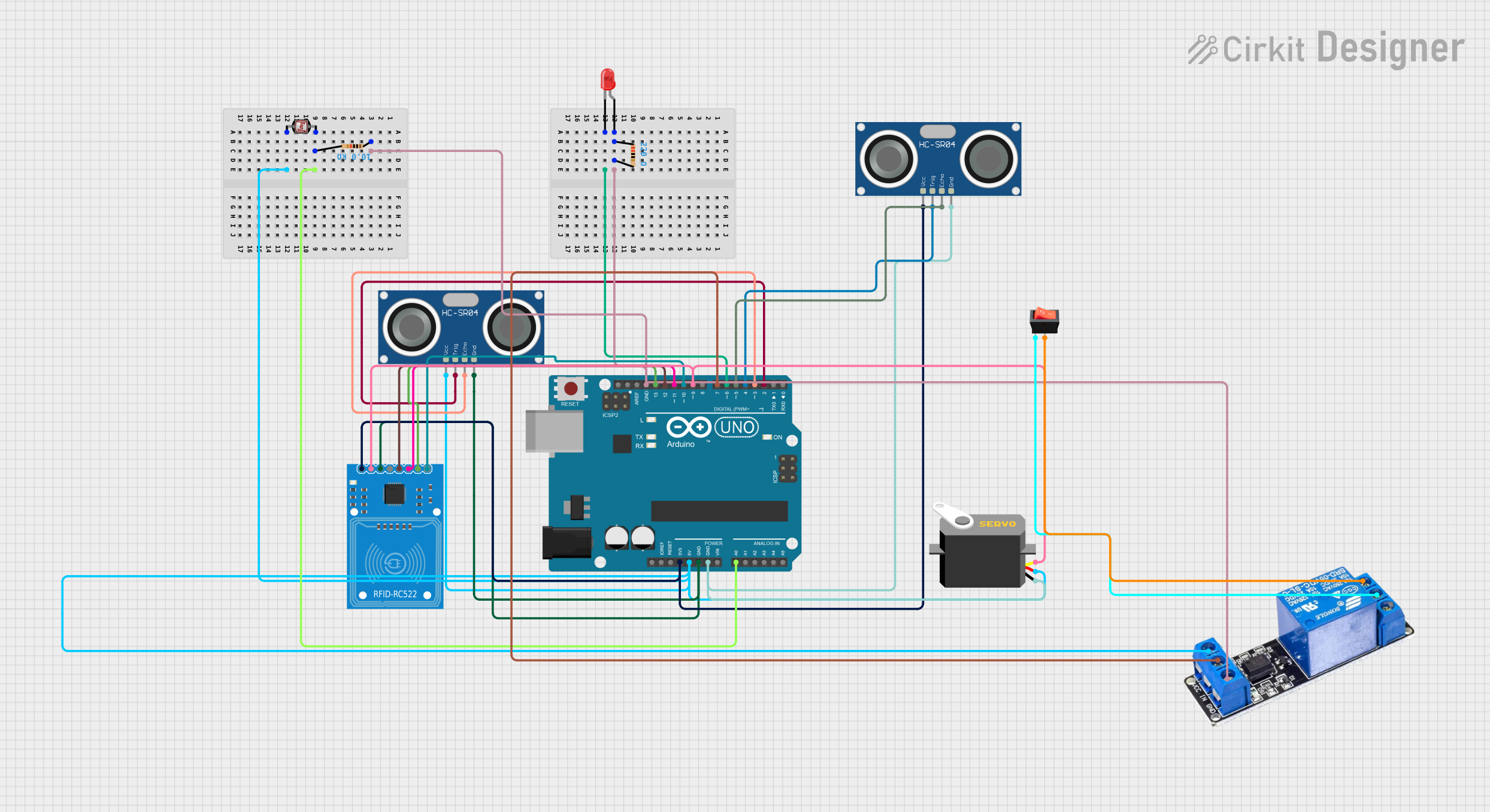
Circuit Documentation
Summary
This document provides a detailed overview of a circuit designed to interface various components with an Arduino UNO microcontroller. The circuit includes input sensors, output actuators, and communication modules. The input sensors consist of a photocell (LDR) and two HC-SR04 ultrasonic sensors. The output actuators are a red LED and a servo motor. Additionally, the circuit integrates an RFID-RC522 module for RFID communication and a 1 Channel 5V Relay for controlling higher power loads. A rocker switch is included for manual control of the relay.
Component List
LED: Two Pin (red)
- Description: A red light-emitting diode (LED) used as an indicator or for illumination.
- Pins: cathode, anode
Arduino UNO
- Description: A microcontroller board based on the ATmega328P, used as the main controller for the circuit.
- Pins: UNUSED, IOREF, Reset, 3.3V, 5V, GND, Vin, A0-A5, SCL, SDA, AREF, D0-D13
Photocell (LDR)
- Description: A light-dependent resistor whose resistance varies with light intensity, used for sensing ambient light levels.
- Pins: pin 0, pin 1
Servo
- Description: An actuator capable of precise angular positioning, used for controlled movement.
- Pins: gnd, vcc, pulse
HC-SR04 Ultrasonic Sensor
- Description: An ultrasonic distance sensor that measures distance by emitting ultrasonic waves and timing their return after reflecting off an object.
- Pins: VCC, TRIG, ECHO, GND
Resistor
- Description: A passive two-terminal electrical component that implements electrical resistance as a circuit element.
- Properties: Resistance (available in 220 Ohms and 10000 Ohms)
RFID-RC522
- Description: An RFID reader/writer module used for wireless communication with RFID tags.
- Pins: SDA, SCK, MOSI, MISO, IRQ, GND, RST, 3.3V
Rocker Switch
- Description: A manual switch used to open or close an electrical circuit.
- Pins: output, input
1 Channel 5V Relay
- Description: An electromechanical switch used to control a high power circuit with a low power signal.
- Pins: OPEN, COM, CLOSE, VCC, SIG, GND
Wiring Details
LED: Two Pin (red)
- Anode: Connected to a 220 Ohm resistor.
- Cathode: Connected to pin D6 of the Arduino UNO.
Arduino UNO
- GND: Common ground for various components including resistors, relay, and sensors.
- 5V: Power supply for the Photocell (LDR), Servo, and HC-SR04 Ultrasonic Sensor.
- 3.3V: Power supply for the RFID-RC522 and one HC-SR04 Ultrasonic Sensor.
- A0: Connected to the Photocell (LDR) through a 10000 Ohm resistor.
- D2-D13: Various digital pins connected to the HC-SR04 Ultrasonic Sensors, RFID-RC522, Servo, and Relay.
Photocell (LDR)
- Pin 0: Connected to the 5V power supply.
- Pin 1: Connected to pin A0 of the Arduino UNO through a 10000 Ohm resistor.
Servo
- VCC: Connected to the 5V power supply.
- GND: Connected to the common ground.
- Pulse: Connected to pin D9 of the Arduino UNO.
HC-SR04 Ultrasonic Sensor
- VCC: Connected to either 5V or 3.3V power supply depending on the sensor.
- TRIG: Connected to pins D2 and D4 of the Arduino UNO for two sensors respectively.
- ECHO: Connected to pins D3 and D5 of the Arduino UNO for two sensors respectively.
- GND: Connected to the common ground.
Resistor
- 220 Ohm: Connected between the anode of the LED and the 5V power supply.
- 10000 Ohm: Connected between pin 1 of the Photocell (LDR) and pin A0 of the Arduino UNO.
RFID-RC522
- 3.3V: Connected to the 3.3V power supply.
- GND: Connected to the common ground.
- RST: Connected to pin D9 of the Arduino UNO.
- SDA, SCK, MOSI, MISO: Connected to pins D10, D13, D11, and D12 of the Arduino UNO respectively.
Rocker Switch
- Input: Connected to the COM terminal of the 1 Channel 5V Relay.
- Output: Connected to the OPEN terminal of the 1 Channel 5V Relay.
1 Channel 5V Relay
- VCC: Connected to the 5V power supply.
- GND: Connected to the common ground.
- SIG: Connected to pin D7 of the Arduino UNO.
- COM: Connected to the input of the rocker switch.
- OPEN: Connected to the output of the rocker switch.
Documented Code
void setup() {
  // put your setup code here, to run once:

}

void loop() {
  // put your main code here, to run repeatedly:

}
The provided code is a template with empty setup() and loop() functions, which are the standard structure for Arduino sketches. The setup() function is intended to contain initialization code that runs once when the microcontroller is powered on or reset. The loop() function is intended to contain the main logic of the program, which runs repeatedly as long as the microcontroller is powered.