
Adjustable DC Power Supply with LM317 and 7-Segment Voltmeter
View and Edit Project In Cirkit Designer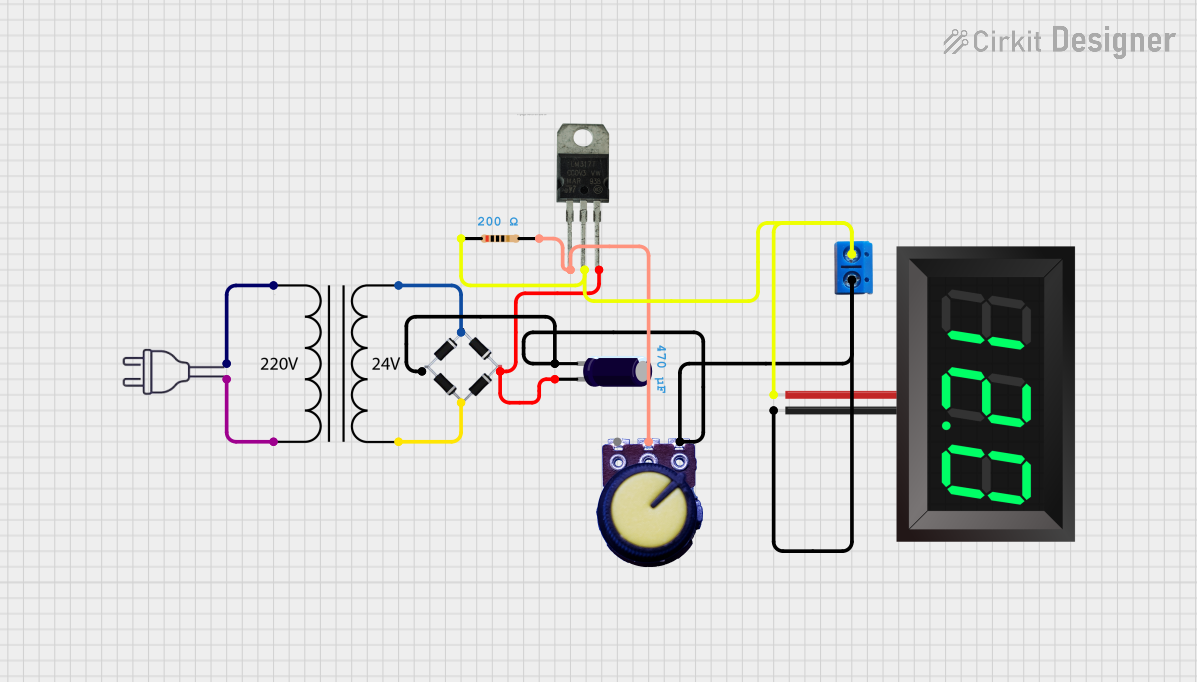
Circuit Documentation
Summary
This document provides a detailed overview of a power supply circuit that converts 220V AC to a regulated DC voltage. The circuit includes a power transformer, bridge rectifier, electrolytic capacitor, potentiometer, LM317 voltage regulator, 7-segment panel voltmeter, and other essential components. The document outlines the components used, their descriptions, wiring details, and any embedded code.
Component List
Power Transformer (220V to 24V)
- Pins: 2 - Primary, 1 - Primary, 3 - Secondary, 4 - Secondary
- Description: Converts 220V AC to 24V AC.
Bridge Rectifier
- Pins: Source_in-, source_out-, source_out+, source_in+
- Description: Converts AC to DC.
Electrolytic Capacitor
- Pins: -, +
- Description: Smooths the rectified DC voltage.
- Properties:
- Capacitance: 0.00047 Farads
Power 220V
- Pins: hot wire, neutral wire
- Description: Provides 220V AC input.
Potentiometer
- Pins: GND, Output, VCC
- Description: Adjusts the output voltage.
LM317
- Pins: ADJ, VO, VI
- Description: Adjustable voltage regulator.
7-Segment Panel Voltmeter
- Pins: V+, V-
- Description: Displays the output voltage.
Terminal PCB 2 Pin
- Pins: Pin A, Pin B
- Description: Provides connection points for external components.
Resistor
- Pins: pin1, pin2
- Description: Limits current.
- Properties:
- Resistance: 200 Ohms
Wiring Details
Power Transformer (220V to 24V)
- 2 - Primary connected to hot wire of Power 220V
- 1 - Primary connected to neutral wire of Power 220V
- 3 - Secondary connected to Source_in- of Bridge Rectifier
- 4 - Secondary connected to source_in+ of Bridge Rectifier
Bridge Rectifier
- Source_in- connected to 3 - Secondary of Power Transformer
- source_in+ connected to 4 - Secondary of Power Transformer
- source_out- connected to GND of Potentiometer, - of Electrolytic Capacitor, V- of 7-Segment Panel Voltmeter, and Pin B of Terminal PCB 2 Pin
- source_out+ connected to + of Electrolytic Capacitor and VI of LM317
Electrolytic Capacitor
- - connected to source_out- of Bridge Rectifier
- + connected to source_out+ of Bridge Rectifier and VI of LM317
Power 220V
- hot wire connected to 2 - Primary of Power Transformer
- neutral wire connected to 1 - Primary of Power Transformer
Potentiometer
- GND connected to source_out- of Bridge Rectifier
- Output connected to ADJ of LM317 and pin2 of Resistor
LM317
- ADJ connected to Output of Potentiometer and pin2 of Resistor
- VO connected to pin1 of Resistor, V+ of 7-Segment Panel Voltmeter, and Pin A of Terminal PCB 2 Pin
- VI connected to source_out+ of Bridge Rectifier and + of Electrolytic Capacitor
7-Segment Panel Voltmeter
- V+ connected to VO of LM317 and Pin A of Terminal PCB 2 Pin
- V- connected to source_out- of Bridge Rectifier and Pin B of Terminal PCB 2 Pin
Terminal PCB 2 Pin
- Pin A connected to VO of LM317 and V+ of 7-Segment Panel Voltmeter
- Pin B connected to source_out- of Bridge Rectifier and V- of 7-Segment Panel Voltmeter
Resistor
- pin1 connected to VO of LM317 and V+ of 7-Segment Panel Voltmeter
- pin2 connected to ADJ of LM317 and Output of Potentiometer
Embedded Code
There is no embedded code for this circuit.
This document provides a comprehensive overview of the power supply circuit, including component descriptions and detailed wiring information.