Cirkit Designer
Your all-in-one circuit design IDE
Home /
Project Documentation
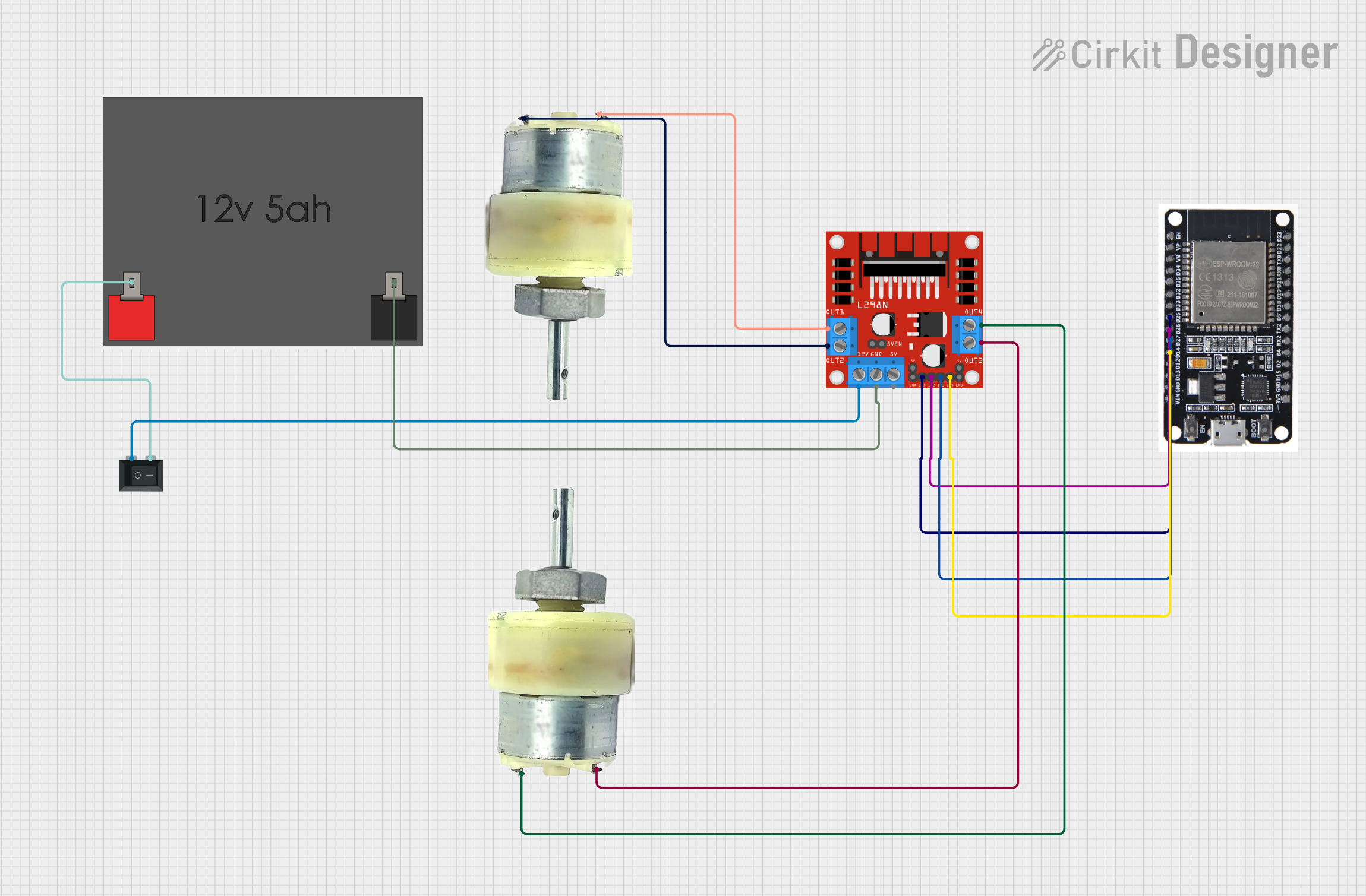
ESP32 and L298N Motor Driver Controlled Dual 12V Geared Motor System
Circuit Documentation
Summary
This document provides a detailed overview of a circuit designed to control two 12V geared motors using an ESP32 microcontroller and an L298N DC motor driver. The circuit is powered by a 12V 5Ah battery and includes a rocker switch for power control.
Component List
ESP32
- Description: A powerful microcontroller with Wi-Fi and Bluetooth capabilities.
- Pins: EN, VP, VN, D34, D35, D32, D33, D25, D26, D27, D14, D12, D13, GND, VIN, 3V3, D15, D2, D4, RX2, TX2, D5, D18, D19, D21, RX0, TX0, D22, D23, BOOT
L298N DC Motor Driver
- Description: A dual H-Bridge motor driver that allows control of two DC motors.
- Pins: OUT1, OUT2, 12V, GND, 5V, OUT3, OUT4, 5V-ENA-JMP-I, 5V-ENA-JMP-O, +5V-J1, +5V-J2, ENA, IN1, IN2, IN3, IN4, ENB
12V Geared Motor (Motor 1)
- Description: A 12V DC motor with a gearbox for increased torque.
- Pins: Terminal 1, Terminal 2
12V Geared Motor (Motor 2)
- Description: A 12V DC motor with a gearbox for increased torque.
- Pins: Terminal 1, Terminal 2
12V 5Ah Battery
- Description: A rechargeable battery providing 12V power.
- Pins: 12v +, 12v -
Rocker Switch (SPST)
- Description: A single-pole single-throw switch for power control.
- Pins: 1, 2
Wiring Details
ESP32
- D25 is connected to IN1 of the L298N DC motor driver.
- D26 is connected to IN2 of the L298N DC motor driver.
- D27 is connected to IN3 of the L298N DC motor driver.
- D14 is connected to IN4 of the L298N DC motor driver.
L298N DC Motor Driver
- IN1 is connected to D25 of the ESP32.
- IN2 is connected to D26 of the ESP32.
- IN3 is connected to D27 of the ESP32.
- IN4 is connected to D14 of the ESP32.
- OUT1 is connected to Terminal 1 of Motor 2.
- OUT2 is connected to Terminal 2 of Motor 2.
- OUT3 is connected to Terminal 2 of Motor 1.
- OUT4 is connected to Terminal 1 of Motor 1.
- 12V is connected to pin 1 of the Rocker Switch.
- GND is connected to 12v - of the 12V 5Ah Battery.
12V Geared Motor (Motor 1)
- Terminal 1 is connected to OUT4 of the L298N DC motor driver.
- Terminal 2 is connected to OUT3 of the L298N DC motor driver.
12V Geared Motor (Motor 2)
- Terminal 1 is connected to OUT1 of the L298N DC motor driver.
- Terminal 2 is connected to OUT2 of the L298N DC motor driver.
12V 5Ah Battery
- 12v + is connected to pin 2 of the Rocker Switch.
- 12v - is connected to GND of the L298N DC motor driver.
Rocker Switch (SPST)
- Pin 1 is connected to 12V of the L298N DC motor driver.
- Pin 2 is connected to 12v + of the 12V 5Ah Battery.
Code
No code is provided for this circuit.