
ESP8266 and SIM800L Based GPS Tracker with I2C LCD Display and Battery Power
View and Edit Project In Cirkit Designer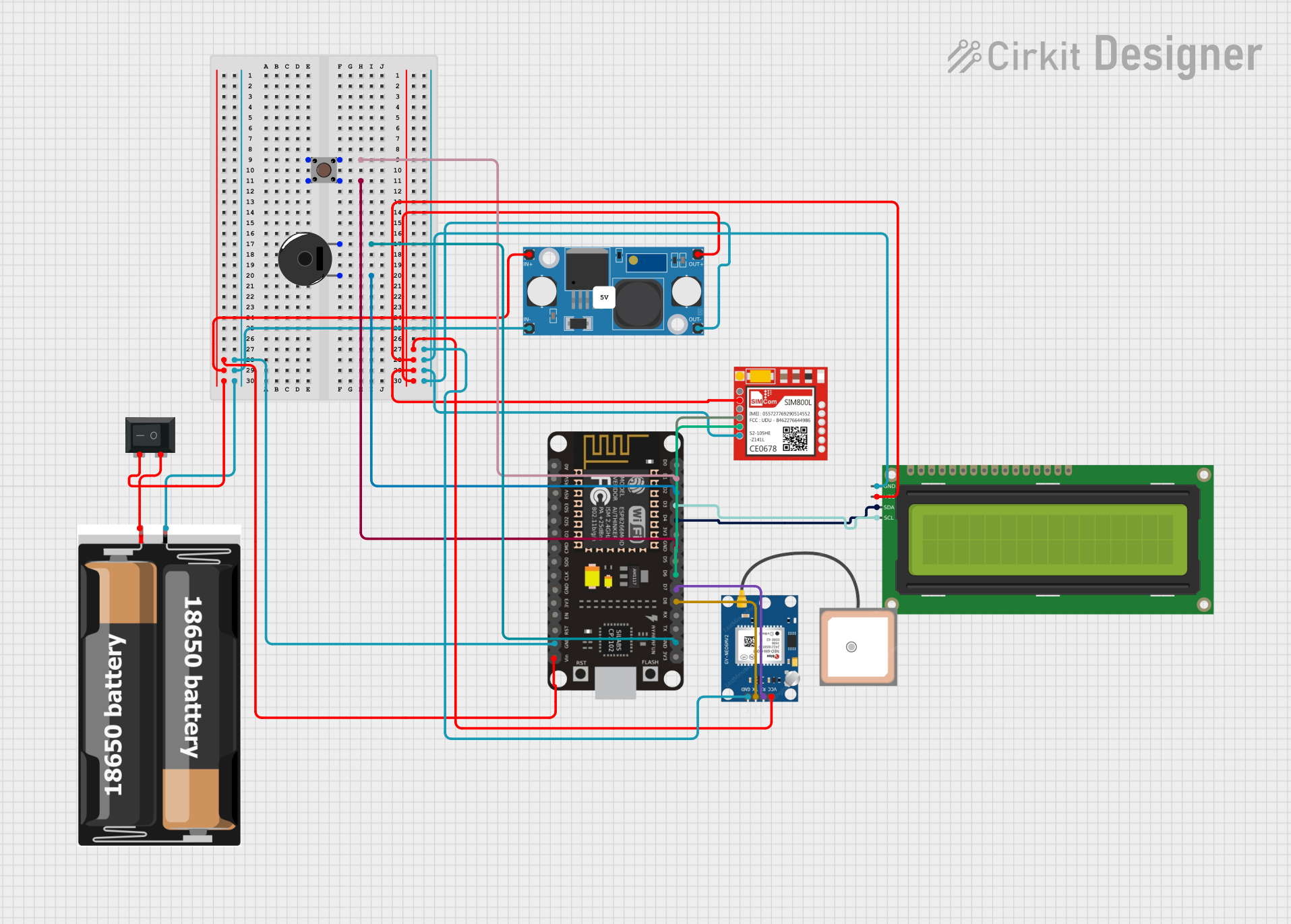
Circuit Documentation
Summary
This document provides a detailed overview of a circuit that includes an ESP8266 NodeMCU, a SIM800L GSM module, a 16x2 I2C LCD, a GPS NEO 6M module, an LM2596 step-down module, a 2x 18650 battery pack, a pushbutton, a piezo buzzer, and a rocker switch. The circuit is designed to integrate these components to perform various functions, including wireless communication, GPS tracking, and user interaction through a button and display.
Component List
ESP8266 NodeMCU
- Description: A low-cost Wi-Fi microcontroller with GPIO, PWM, ADC, I2C, and UART capabilities.
- Pins: D0, D1, D2, D3, D4, 3V3, GND, D5, D6, D7, D8, RX, TX, A0, RSV, SD3, SD2, SD1, CMD, SD0, CLK, EN, RST, VIN
SIM800L
- Description: A GSM/GPRS module for cellular communication.
- Pins: NET, RST, VCC, RXD, TXD, GND
16x2 I2C LCD
- Description: A 16x2 character LCD with I2C interface.
- Pins: GND, VCC, SDA, SCL
GPS NEO 6M
- Description: A GPS module for location tracking.
- Pins: VCC, RX, TX, GND
LM2596 Step Down Module
- Description: A DC-DC buck converter for voltage regulation.
- Pins: OUT-, OUT+, IN-, IN+
2x 18650 Battery Pack
- Description: A battery pack holding two 18650 lithium-ion cells.
- Pins: vcc, gnd
Pushbutton
- Description: A simple pushbutton switch.
- Pins: Pin 3 (out), Pin 4 (out), Pin 1 (in), Pin 2 (in)
Piezo Buzzer
- Description: A piezoelectric buzzer for sound output.
- Pins: pin 1, pin 2
Rocker Switch (SPST)
- Description: A single-pole single-throw rocker switch.
- Pins: 1, 2
Wiring Details
ESP8266 NodeMCU
- D1 connected to Pushbutton Pin 4 (out)
- GND connected to Pushbutton Pin 2 (in)
- GND connected to Piezo Buzzer pin 2
- D2 connected to Piezo Buzzer pin 1
- VIN connected to LM2596 Step Down Module IN+ and Rocker Switch (SPST) pin 2
- GND connected to LM2596 Step Down Module IN- and 2x 18650 gnd
- D3 connected to 16x2 I2C LCD SCL
- D4 connected to 16x2 I2C LCD SDA
- D5 connected to Sim800l RXD
- D6 connected to Sim800l TXD
- D7 connected to GPS NEO 6M RX
- D8 connected to GPS NEO 6M TX
SIM800L
- VCC connected to LM2596 Step Down Module OUT+
- GND connected to LM2596 Step Down Module OUT-
- RXD connected to ESP8266 NodeMCU D5
- TXD connected to ESP8266 NodeMCU D6
16x2 I2C LCD
- VCC connected to LM2596 Step Down Module OUT+
- GND connected to LM2596 Step Down Module OUT-
- SDA connected to ESP8266 NodeMCU D4
- SCL connected to ESP8266 NodeMCU D3
GPS NEO 6M
- VCC connected to LM2596 Step Down Module OUT+
- GND connected to LM2596 Step Down Module OUT-
- RX connected to ESP8266 NodeMCU D7
- TX connected to ESP8266 NodeMCU D8
LM2596 Step Down Module
- OUT+ connected to GPS NEO 6M VCC, 16x2 I2C LCD VCC, Sim800l VCC
- OUT- connected to GPS NEO 6M GND, 16x2 I2C LCD GND, Sim800l GND
- IN+ connected to ESP8266 NodeMCU VIN and Rocker Switch (SPST) pin 2
- IN- connected to ESP8266 NodeMCU GND and 2x 18650 gnd
2x 18650 Battery Pack
- vcc connected to Rocker Switch (SPST) pin 1
- gnd connected to LM2596 Step Down Module IN- and ESP8266 NodeMCU GND
Pushbutton
- Pin 4 (out) connected to ESP8266 NodeMCU D1
- Pin 2 (in) connected to ESP8266 NodeMCU GND
Piezo Buzzer
- pin 2 connected to ESP8266 NodeMCU GND
- pin 1 connected to ESP8266 NodeMCU D2
Rocker Switch (SPST)
- pin 1 connected to 2x 18650 vcc
- pin 2 connected to ESP8266 NodeMCU VIN and LM2596 Step Down Module IN+
Documented Code
ESP8266 NodeMCU Code
void setup() {
  // put your setup code here, to run once:

}

void loop() {
  // put your main code here, to run repeatedly:

}
16x2 I2C LCD Code
void setup() {
  // put your setup code here, to run once:

}

void loop() {
  // put your main code here, to run repeatedly:

}
This documentation provides a comprehensive overview of the circuit, including the components used, their wiring details, and the code for the microcontrollers.