Cirkit Designer
Your all-in-one circuit design IDE
Home /
Project Documentation
Arduino UNO Based Ammeter with LCD Display
Circuit Documentation
Summary of the Circuit
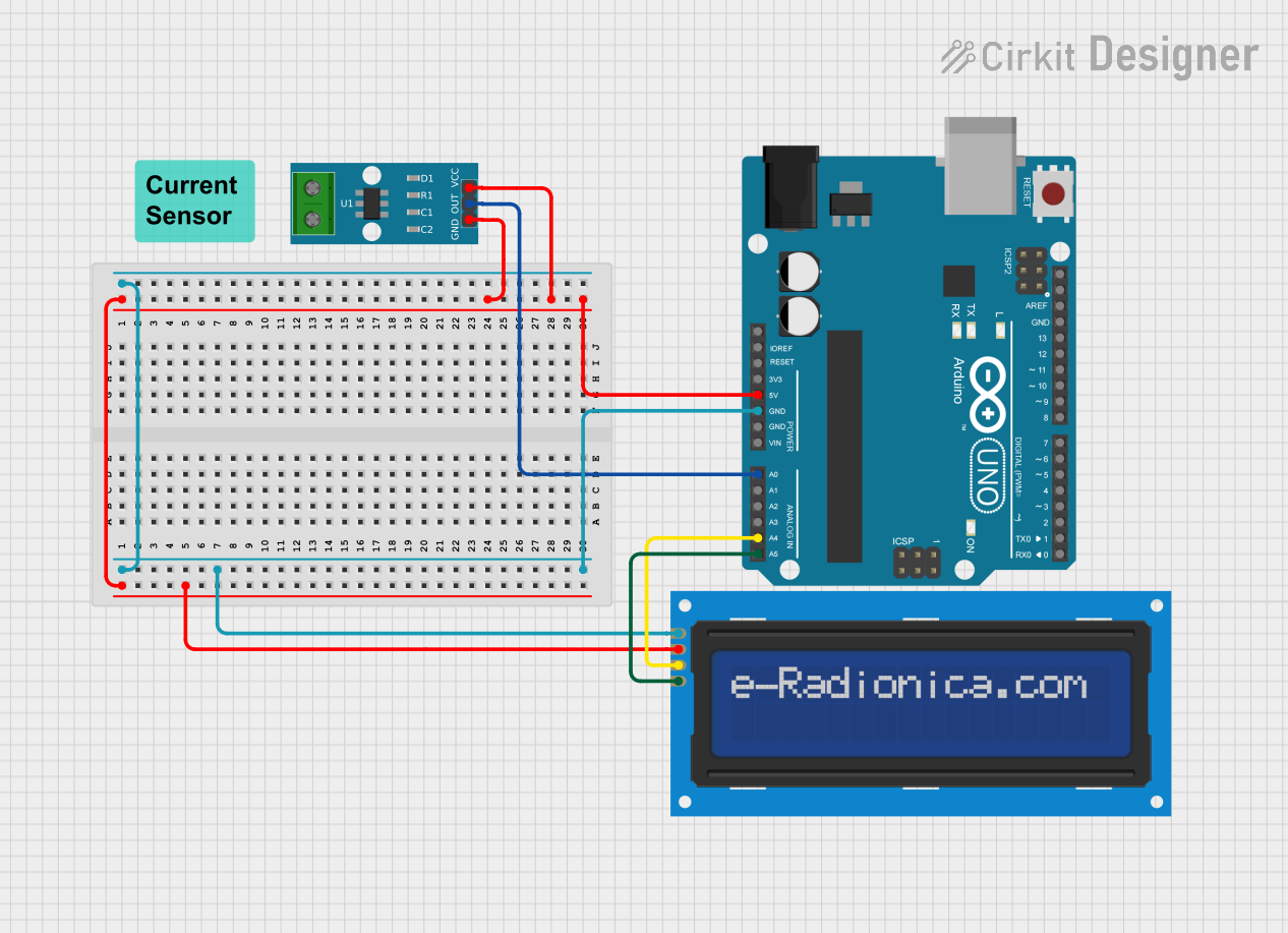
This circuit is designed to measure current using an ACS712 Current Sensor and display the measured value on an LCD screen. The Arduino UNO serves as the central microcontroller unit to process the sensor data and control the LCD display via I2C communication. The LCD screen is a 16x2 character display that provides a user-friendly interface to display the current readings. The ACS712 Current Sensor is capable of measuring current and provides an analog output that is read by the Arduino UNO.
Component List
Arduino UNO
- Description: A microcontroller board based on the ATmega328P.
- Purpose: Acts as the central processing unit for the circuit, reads sensor data, and controls the LCD display.
LCD screen 16x2 I2C
- Description: An alphanumeric liquid crystal display with an I2C interface.
- Purpose: Displays the current measurements in a human-readable format.
ACS712 Current Sensor 5A 20A 30A
- Description: A hall-effect-based linear current sensor.
- Purpose: Measures the current flowing through the circuit and provides an analog voltage output proportional to the current.
Wiring Details
Arduino UNO
- 5V: Provides power to the LCD screen and ACS712 Current Sensor.
- GND: Common ground for the circuit.
- A0: Reads the analog voltage output from the ACS712 Current Sensor.
- A4 (SDA): I2C data line for LCD screen communication.
- A5 (SCL): I2C clock line for LCD screen communication.
LCD screen 16x2 I2C
- VCC: Connected to the 5V output from the Arduino UNO.
- GND: Connected to the ground (GND) on the Arduino UNO.
- SDA: Connected to the A4 pin on the Arduino UNO for I2C data.
- SCL: Connected to the A5 pin on the Arduino UNO for I2C clock.
ACS712 Current Sensor 5A 20A 30A
- VCC: Connected to the 5V output from the Arduino UNO.
- GND: Connected to the ground (GND) on the Arduino UNO.
- OUT: Connected to the A0 pin on the Arduino UNO to read the current measurement.
Documented Code
#include <Wire.h>                  // Include the Wire library for I2C communication
#include <LiquidCrystal_I2C.h>     // Include the LiquidCrystal_I2C library for controlling the LCD

// Initialize the LCD with the I2C address 0x27, 16 columns, and 2 rows
LiquidCrystal_I2C lcd(0x27, 16, 2);

void setup() {
  Serial.begin(9600);              // Start serial communication at a baud rate of 9600
  lcd.begin(16, 2);                // Initialize the LCD dimensions (16 columns x 2 rows)
  lcd.backlight();                 // Turn on the LCD backlight for visibility
  lcd.print("Ammeter Ready");      // Display a startup message on the LCD
  delay(2000);                     // Wait for 2 seconds to allow the message to be read
  lcd.clear();                     // Clear the display after the delay
}

void loop() {
  // Read the output voltage from the current sensor (connected to analog pin A0)
  int sensorValue = analogRead(A0);

  // Convert the sensor value (0-1023) to voltage (0-5V)
  float voltage = sensorValue * (5.0 / 1023.0);

  // Calculate current based on the sensor output
  // Assuming the sensor outputs 2.5V at 0A and has a sensitivity of 0.1V/A
  float current = (voltage - 2.5) / 0.1;

  // Display the current value on the LCD
  lcd.setCursor(0, 0);             // Set cursor to the first row (line 0)
  lcd.print("Current: ");           // Print the label "Current: "
  lcd.setCursor(0, 1);             // Move the cursor to the second row (line 1)
  lcd.print(current, 2);            // Print the current value with 2 decimal places
  lcd.print(" A");                  // Append the unit "A" for amperes

  // Output the current value to the Serial Monitor
  Serial.print("Current: ");        // Print label for the Serial Monitor
  Serial.print(current, 2);         // Print current value with 2 decimal places
  Serial.println(" A");             // Append the unit "A" for amperes to the Serial output

  delay(1000);                      // Delay for 1 second before taking the next reading
}
This code initializes the LCD and sets up the Arduino to read the current sensor's output. It then continuously reads the sensor, calculates the current, and displays the result on the LCD and the Serial Monitor.