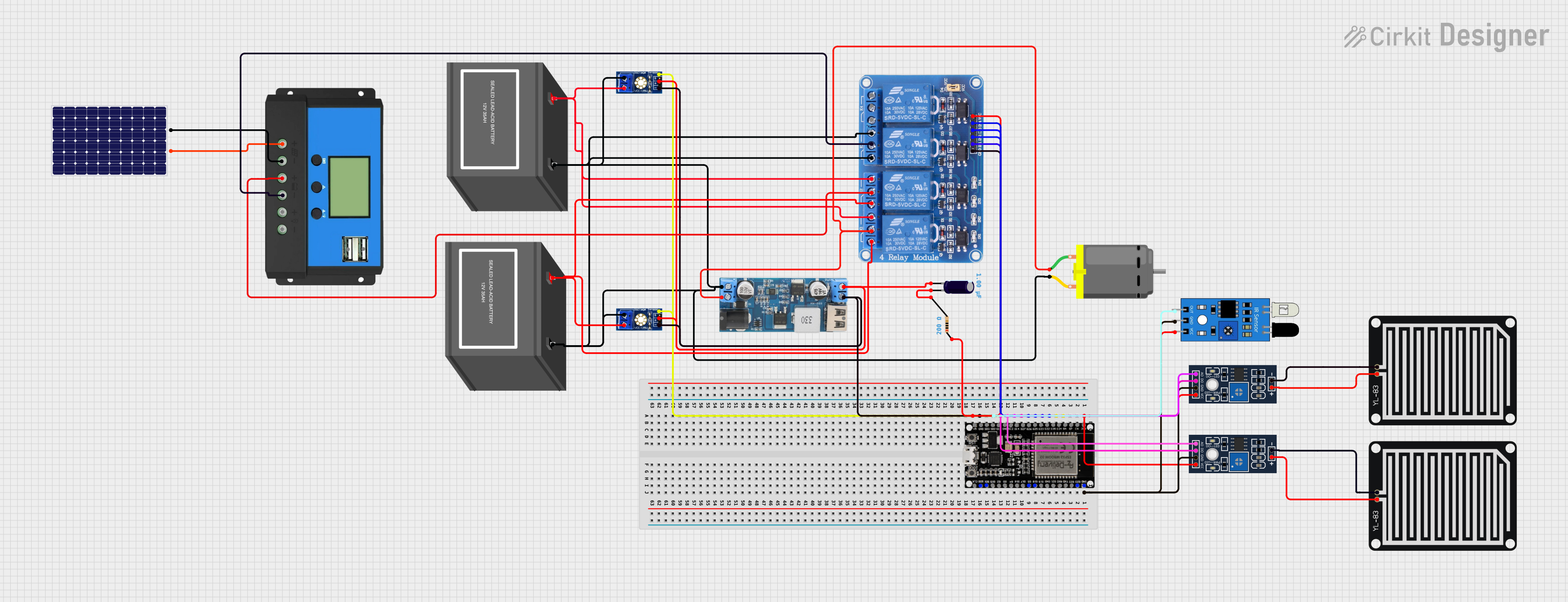
ESP32-Based Rain and Obstacle Detection System with Relay Motor Control

Circuit Documentation
Summary
The circuit is designed to monitor environmental conditions such as voltage levels and rain presence while controlling a DC motor based on sensor inputs. It includes a voltage sensing mechanism, rain detection, and an IR sensor for object detection. The circuit uses an ESP32 microcontroller to process sensor data and control a 4-channel relay module that interfaces with a DC motor. Power management is handled by a 12V battery, a step-down power converter, and a solar charge controller connected to a solar panel. The circuit also includes a voltage sensor, an IR sensor, two rain sensor modules (detection and control boards), and passive components like a resistor and an electrolytic capacitor.
Component List
Power Components
- 12V Battery (mini): Provides the main power source for the circuit.
- 12v to 5v Step Down Power Converter: Converts the 12V battery voltage to a regulated 5V output.
- Solar Charge Controller: Manages the charging of the battery from the solar panel.
- Solar Panel: Generates electrical power from sunlight to charge the battery.
Sensors
- Voltage Sensor DC: Measures the voltage level of the battery.
- IR Sensor: Detects the presence of objects using infrared light.
- YL-83 Rain Sensor - Detection Board: Detects rainwater.
- YL-83 Rain Sensor - Control Board: Processes the signal from the detection board and provides digital and analog outputs.
Actuators
- DC Motor: Converts electrical energy into mechanical motion.
- Relay 4 Channel 5v: Electrically operated switches that control the power to the DC motor.
Microcontroller
- ESP32 38 PINS: A microcontroller with Wi-Fi and Bluetooth capabilities that reads sensor data and controls the relays.
Passive Components
- Electrolytic Capacitor: Used for filtering and stabilizing the power supply.
- Resistor: Limits the current or divides voltages within the circuit.
Wiring Details
Power Components
12V Battery (mini):
+to voltage sensor VCC, Relay 4 Channel 5v NO1, NO2, and step-down converter VIN+.-to step-down converter VIN-, DC Motor pin 2, voltage sensor GND, Relay 4 Channel 5v NO3, NC3, and another 12V Battery (mini)-.
12v to 5v Step Down Power Converter:
VIN 9v-36vnot connected.VIN+to DC Motor pin 1 and Relay 4 Channel 5v COM1.VIN-to 12V Battery (mini)-.USB OUTPUT 5Vnot connected.5v OUTPUTto voltage sensor vcc and Electrolytic Capacitor-.GNDto voltage sensor gnd, Relay 4 Channel 5v GND.
Solar Charge Controller:
- No specific pin connections listed, but connected to solar panel and Relay 4 Channel 5v COM2, COM3.
Solar Panel:
+to Solar Charge Controller.-to Solar Charge Controller.
Sensors
Voltage Sensor DC:
signalnot connected.vccto step-down converter 5v OUTPUT.gndto step-down converter GND.GNDto 12V Battery (mini)-.VCCto 12V Battery (mini)+.
IR Sensor:
outnot connected.gndto ESP32 GND.vccto YL-83 Rain Sensor - Control Board VCC.
YL-83 Rain Sensor - Detection Board:
POSto YL-83 Rain Sensor - Control Board POS.NEGto YL-83 Rain Sensor - Control Board NEG.
YL-83 Rain Sensor - Control Board:
VCCto IR Sensor vcc.GNDto ESP32 GND.DOnot connected.AOnot connected.POSto YL-83 Rain Sensor - Detection Board POS.NEGto YL-83 Rain Sensor - Detection Board NEG.
Actuators
DC Motor:
pin 1to step-down converter VIN+.pin 2to 12V Battery (mini)-.
Relay 4 Channel 5v:
GNDto step-down converter GND.IN1not connected.IN2not connected.IN3not connected.IN4not connected.VCCto Resistor pin1.COM1to step-down converter VIN+.COM2to Solar Charge Controller.COM3to Solar Charge Controller.COM4not connected.NO1to 12V Battery (mini)+.NO2to 12V Battery (mini)+.NO3to 12V Battery (mini)-.NO4not connected.NC1to 12V Battery (mini)+.NC2to 12V Battery (mini)+.NC3to 12V Battery (mini)-.NC4not connected.
Microcontroller
- ESP32 38 PINS:
GNDto IR Sensor gnd, YL-83 Rain Sensor - Control Board GND.
Passive Components
Electrolytic Capacitor:
+to Resistor pin2.-to step-down converter 5v OUTPUT.
Resistor:
pin1to Relay 4 Channel 5v VCC.pin2to Electrolytic Capacitor+.
Documented Code
#include <Arduino.h>

// Pin Definitions
const int voltageSensorPin = 34;    // Voltage sensor analog input
const int rainSensorPin = 35;       // Rain sensor analog input
const int irSensorPin = 32;         // IR sensor digital input
const int relay1Pin = 26;           // Relay channel 1 for DC motor
const int relay2Pin = 27;           // Relay channel 2 (for future use)
const int relay3Pin = 14;           // Relay channel 3 (for future use)
const int relay4Pin = 12;           // Relay channel 4 (for future use)

// Voltage sensor calibration constants
const float voltageReference = 3.3; // Reference voltage of ESP32 ADC
const int resolution = 4095;        // ADC resolution
const float voltageDividerRatio = 5.7; // Ratio of the voltage divider used in the sensor

void setup() {
  // Initialize serial communication
  Serial.begin(115200);

  // Set pin modes
  pinMode(voltageSensorPin, INPUT);
  pinMode(rainSensorPin, INPUT);
  pinMode(irSensorPin, INPUT);
  pinMode(relay1Pin, OUTPUT);
  pinMode(relay2Pin, OUTPUT);
  pinMode(relay3Pin, OUTPUT);
  pinMode(relay4Pin, OUTPUT);

  // Initialize relays to be off
  digitalWrite(relay1Pin, LOW);
  digitalWrite(relay2Pin, LOW);
  digitalWrite(relay3Pin, LOW);
  digitalWrite(relay4Pin, LOW);
}

void loop() {
  // Voltage sensing
  int voltageSensorValue = analogRead(voltageSensorPin);
  float batteryVoltage = (voltageSensorValue * voltageReference / resolution) * voltageDividerRatio;
  Serial.print("Battery Voltage: ");
  Serial.println(batteryVoltage);

  // Rain detection
  int rainSensorValue = analogRead(rainSensorPin);
  Serial.print("Rain Sensor Value: ");
  Serial.println(rainSensorValue);

  // IR sensor detection
  int irSensorValue = digitalRead(irSensorPin);
  Serial.print("IR Sensor State: ");
  Serial.println(irSensorValue);

  // Motor control based on rain and IR sensor input
  if (rainSensorValue > 500) {
    // If rain detected, stop the motor
    digitalWrite(relay1Pin, LOW);
    Serial.println("Rain detected, motor stopped.");
  } else if (irSensorValue == HIGH) {
    // If no rain and IR sensor detects an object, start the motor
    digitalWrite(relay1Pin, HIGH);
    Serial.println("IR detected, motor running.");
  } else {
    // If no rain and no IR detection, keep motor off
    digitalWrite(relay1Pin, LOW);
    Serial.println("No rain, no IR, motor stopped.");
  }

  // Add delays to reduce serial output spamming
  delay(1000);
}
This code is designed to run on an ESP32 microcontroller. It initializes the necessary pins for reading from the voltage and rain sensors, as well as for controlling the relays connected to the DC motor. The loop function reads