
Arduino UNO Based Wireless Communication System with NRF24L01 Modules
View and Edit Project In Cirkit Designer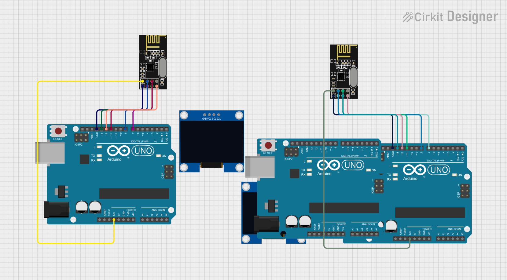
Circuit Documentation
Summary
This circuit comprises two Arduino UNO microcontrollers, each interfaced with an NRF24L01 transceiver module, and two 128x64 OLED displays. One Arduino UNO is configured as a transmitter, sending "Hello World" messages to the receiver, which is the second Arduino UNO. The NRF24L01 modules facilitate wireless communication between the two Arduinos. The OLED displays are not detailed in the wiring information and thus are assumed to be unused in the current configuration.
Component List
Microcontrollers
- Arduino UNO (x3)
- Microcontroller board based on the ATmega328P.
- It has 14 digital input/output pins, 6 analog inputs, a 16 MHz quartz crystal, a USB connection, a power jack, an ICSP header, and a reset button.
Transceivers
- NRF24L01 (x2)
- A 2.4GHz ISM band transceiver.
- Includes features such as 125 channels, multi-point communication, and frequency hopping.
Displays
- 128x64 OLED Display (I2C IIC SPI Serial) (x2)
- A small display for showing graphics and text.
- Communicates via I2C or SPI.
Wiring Details
Arduino UNO (Transmitter)
- 3.3V to NRF24L01 VCC (3V)
- GND to NRF24L01 GND
- D13 (SCK) to NRF24L01 SCK
- D12 (MISO) to NRF24L01 MISO
- D11 (MOSI) to NRF24L01 MOSI
- D8 (CSN) to NRF24L01 CSN
- D7 (CE) to NRF24L01 CE
Arduino UNO (Receiver)
- 3.3V to NRF24L01 VCC (3V)
- GND to NRF24L01 GND
- D13 (SCK) to NRF24L01 SCK
- D12 (MISO) to NRF24L01 MISO
- D11 (MOSI) to NRF24L01 MOSI
- D8 (CSN) to NRF24L01 CSN
- D7 (CE) to NRF24L01 CE
Arduino UNO (Unused)
- No wiring details provided.
NRF24L01
- VCC (3V) connected to 3.3V on Arduino UNO
- GND connected to GND on Arduino UNO
- CE connected to D7 on Arduino UNO
- CSN connected to D8 on Arduino UNO
- SCK connected to D13 on Arduino UNO
- MISO connected to D12 on Arduino UNO
- MOSI connected to D11 on Arduino UNO
128x64 OLED Display (I2C IIC SPI Serial)
- No wiring details provided.
Documented Code
Arduino UNO (Transmitter)
/*
 * This Arduino sketch configures an Arduino UNO to work as an NRF24L01
 * transmitter. The NRF24L01 module is connected to the Arduino UNO as follows:
 * CE  -> D7
 * CSN -> D8
 * SCK -> D13
 * MOSI -> D11
 * MISO -> D12
 * VCC -> 3.3V
 * GND -> GND
 * This code sends a 'Hello World' message every second to the receiver.
 */

#include <SPI.h>
#include <nRF24L01.h>
#include <RF24.h>

// NRF24L01 pin definitions
#define CE_PIN 7
#define CSN_PIN 8

// Create an RF24 object
RF24 radio(CE_PIN, CSN_PIN);

// Address for the communication
const byte address[6] = "00001";

void setup() {
  // Initialize the serial communication
  Serial.begin(9600);
  // Initialize the NRF24L01 radio
  radio.begin();
  // Set the address
  radio.openWritingPipe(address);
  // Set the radio to transmitter mode
  radio.setPALevel(RF24_PA_MIN);
  // Stop listening
  radio.stopListening();
}

void loop() {
  // Data to be sent
  const char text[] = "Hello World";
  // Send the data
  radio.write(&text, sizeof(text));
  // Print the sent data to the serial monitor
  Serial.println(text);
  // Wait for a second before sending the next data
  delay(1000);
}
Arduino UNO (Receiver)
/*
 * This Arduino sketch configures an Arduino UNO to work as an NRF24L01 receiver.
 * The NRF24L01 module is connected to the Arduino UNO as follows:
 * CE  -> D7
 * CSN -> D8
 * SCK -> D13
 * MOSI -> D11
 * MISO -> D12
 * VCC -> 3.3V
 * GND -> GND
 */

#include <SPI.h>
#include <nRF24L01.h>
#include <RF24.h>

// NRF24L01 pin definitions
#define CE_PIN 7
#define CSN_PIN 8

// Create an RF24 object
RF24 radio(CE_PIN, CSN_PIN);

// Address for the communication
const byte address[6] = "00001";

void setup() {
  // Initialize the serial communication
  Serial.begin(9600);
  // Initialize the NRF24L01 radio
  radio.begin();
  // Set the address
  radio.openReadingPipe(0, address);
  // Set the radio to receiver mode
  radio.setPALevel(RF24_PA_MIN);
  // Start listening
  radio.startListening();
}

void loop() {
  // Check if data is available to read
  if (radio.available()) {
    char text[32] = {0};
    // Read the data
    radio.read(&text, sizeof(text));
    // Print the received data to the serial monitor
    Serial.println(text);
  }
}
Arduino UNO (Unused)
void setup() {
  // put your setup code here, to run once:

}

void loop() {
  // put your main code here, to run repeatedly:

}
The third Arduino UNO and the OLED displays do not have associated code or wiring details in the provided documentation.