
NAND Gate Controlled LED Circuit with Pushbutton and Capacitor
View and Edit Project In Cirkit Designer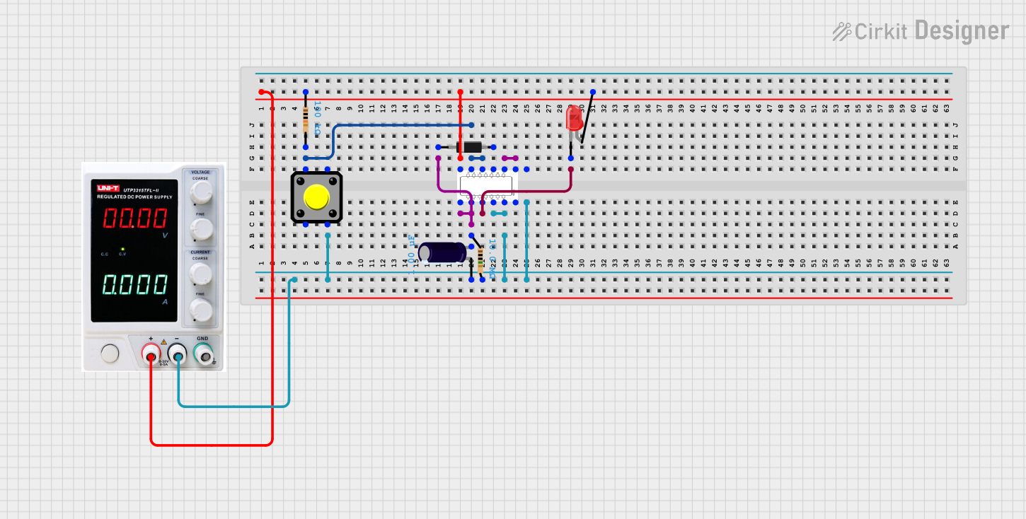
Circuit Documentation
Summary
This document provides a detailed description of a digital circuit that includes a NAND gate IC (SN74LS00N), a power supply, resistors, a pushbutton, a diode, an electrolytic capacitor, and an LED. The circuit is designed to demonstrate basic digital logic and passive component interactions.
Component List
SN74LS00N (NAND Gate IC)
- Description: Quad 2-input NAND gate
- Pins: 1A, 1B, 1Y, 2A, 2B, 2Y, GND, VCC, 4A, 4B, 4Y, 3A, 3B, 3Y
Power Supply
- Description: Provides power to the circuit
- Pins: +, -, GND
Resistor (100k Ohms)
- Description: Limits current flow
- Pins: pin1, pin2
- Properties: Resistance = 100k Ohms
Resistor (10M Ohms)
- Description: Limits current flow
- Pins: pin1, pin2
- Properties: Resistance = 10M Ohms
Pushbutton
- Description: Provides a manual input to the circuit
- Pins: Pin 1, Pin 2, Pin 3, Pin 4
Diode
- Description: Allows current to flow in one direction
- Pins: cathode, anode
Electrolytic Capacitor
- Description: Stores electrical energy
- Pins: +, -
- Properties: Capacitance = 1 µF
LED: Two Pin (red)
- Description: Emits light when current flows through it
- Pins: cathode, anode
Wiring Details
SN74LS00N (NAND Gate IC)
- 4A is connected to 4B and pin2 of the 100k Ohm Resistor and Pin 1 of the Pushbutton.
- 2A is connected to 2B, GND, - of the Electrolytic Capacitor, pin2 of the 10M Ohm Resistor, and - of the Power Supply.
- 1A is connected to 1B, + of the Electrolytic Capacitor, pin1 of the 10M Ohm Resistor, and cathode of the Diode.
- VCC is connected to pin1 of the 100k Ohm Resistor, anode of the LED, and + of the Power Supply.
- 1Y is connected to cathode of the LED.
- 3A is connected to 3B.
- 4Y is connected to anode of the Diode.
Power Supply
- + is connected to VCC of the SN74LS00N, pin1 of the 100k Ohm Resistor, and anode of the LED.
- - is connected to 2A, 2B, GND of the SN74LS00N, - of the Electrolytic Capacitor, and pin2 of the 10M Ohm Resistor.
Resistor (100k Ohms)
- pin1 is connected to VCC of the SN74LS00N, anode of the LED, and + of the Power Supply.
- pin2 is connected to 4A, 4B of the SN74LS00N, and Pin 1 of the Pushbutton.
Resistor (10M Ohms)
- pin1 is connected to 1A, 1B of the SN74LS00N, + of the Electrolytic Capacitor, and cathode of the Diode.
- pin2 is connected to 2A, 2B, GND of the SN74LS00N, - of the Electrolytic Capacitor, and - of the Power Supply.
Pushbutton
- Pin 1 is connected to 4A, 4B of the SN74LS00N, and pin2 of the 100k Ohm Resistor.
- Pin 3 is connected to - of the Electrolytic Capacitor, pin2 of the 10M Ohm Resistor, 2A, 2B, GND of the SN74LS00N, and - of the Power Supply.
Diode
- cathode is connected to 1A, 1B of the SN74LS00N, + of the Electrolytic Capacitor, and pin1 of the 10M Ohm Resistor.
- anode is connected to 4Y of the SN74LS00N.
Electrolytic Capacitor
- + is connected to 1A, 1B of the SN74LS00N, pin1 of the 10M Ohm Resistor, and cathode of the Diode.
- - is connected to 2A, 2B, GND of the SN74LS00N, pin2 of the 10M Ohm Resistor, and - of the Power Supply.
LED: Two Pin (red)
- anode is connected to VCC of the SN74LS00N, pin1 of the 100k Ohm Resistor, and + of the Power Supply.
- cathode is connected to 1Y of the SN74LS00N.
Code
There is no microcontroller code associated with this circuit.