
Arduino and ESP8266-Based Smart Power Monitoring System with Wi-Fi Connectivity
View and Edit Project In Cirkit Designer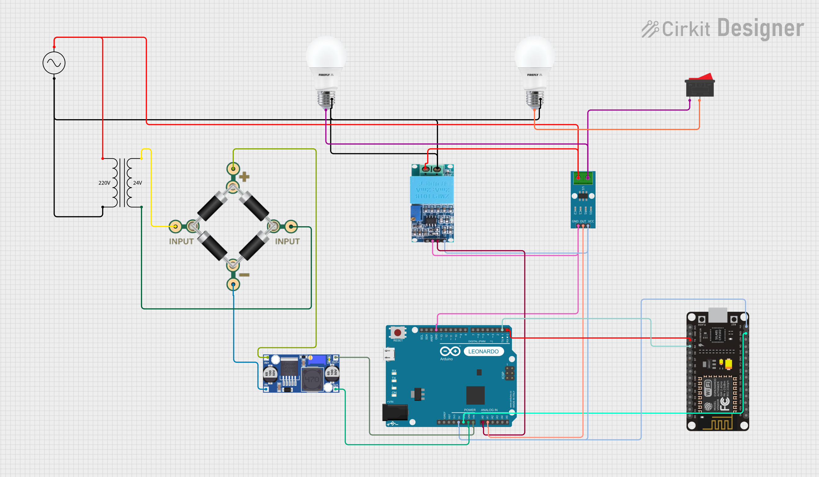
Circuit Documentation
Summary
This circuit is designed to monitor and control electrical parameters such as voltage, current, and power. It utilizes various sensors and microcontrollers to measure these parameters and communicate the data to a remote server. The main components include an AC supply, bulbs, current and voltage sensors, a power transformer, a bridge rectifier, a buck converter, a rocker switch, an Arduino Leonardo, and an ESP8266 NodeMCU.
Component List
AC Supply
- Pins: +ve, -ve
- Description: Provides AC power to the circuit.
Bulb
- Pins: +, -
- Description: Acts as a load in the circuit.
ZMPT101B
- Pins: OUT, GND, VCC, NEUTRO, FASE
- Description: Voltage sensor for measuring AC voltage.
ACS712 Current Sensor 5A 20A 30A
- Pins: 1, 2, GND, OUT, VCC
- Description: Current sensor for measuring AC current.
Bridge Rectifier - 1N4007
- Pins: 1 INPUT, 2 INPUT, + PIN, - PIN
- Description: Converts AC to DC.
Rocker Switch
- Pins: 1, 2
- Description: Used to control the connection of the bulbs.
Arduino Leonardo (Rev3b)
- Pins: D0/RX, D1/TX, D2/SDA, D3 PWM/SCL, D4/A6, D5 PWM, D6 PWM/A7, D7, n.c., IOREF, RESET, 3V3, 5V, GND, VIN, A0, A1, A2, A3, A4, A5, D8/A8, D9 PWM/A9, D10 PWM/A10, D11 PWM, D12/A11, D13 PWM, AREF, SDA, SCL
- Description: Microcontroller for processing sensor data and communicating with the ESP8266.
Power Transformer (220V to 24V)
- Pins: 2 - Primary, 1 - Primary, 3 - Secondary, 4 - Secondary
- Description: Steps down the AC voltage from 220V to 24V.
ESP8266 NodeMCU
- Pins: D0, D1, D2, D3, D4, 3V3, GND, D5, D6, D7, D8, RX, TX, A0, RSV, SD3, SD2, SD1, CMD, SD0, CLK, EN, RST, VIN
- Description: Wi-Fi module for sending data to a remote server.
Buck Converter
- Pins: IN+, IN-, OUT+, OUT-
- Description: Converts DC voltage to a lower level.
Wiring Details
AC Supply
+ve is connected to:
- FASE of ZMPT101B
- 1 - Primary of Power Transformer
- 2 of ACS712 Current Sensor
-ve is connected to:
- NEUTRO of ZMPT101B
- 2 - Primary of Power Transformer
- - of both Bulbs
Bulb 1
+ is connected to:
- 1 of Rocker Switch
- 1 of ACS712 Current Sensor
- is connected to:
- -ve of AC Supply
Bulb 2
+ is connected to:
- 2 of Rocker Switch
- is connected to:
- -ve of AC Supply
ZMPT101B
OUT is connected to:
- A0 of Arduino Leonardo
GND is connected to:
- GND of Arduino Leonardo
- GND of ACS712 Current Sensor
VCC is connected to:
- VIN of ESP8266 NodeMCU
- 5V of Arduino Leonardo
- VCC of ACS712 Current Sensor
FASE is connected to:
- +ve of AC Supply
NEUTRO is connected to:
- -ve of AC Supply
ACS712 Current Sensor
1 is connected to:
- + of Bulb 1
- 1 of Rocker Switch
2 is connected to:
- +ve of AC Supply
GND is connected to:
- GND of Arduino Leonardo
- GND of ZMPT101B
OUT is connected to:
- A1 of Arduino Leonardo
VCC is connected to:
- VCC of ZMPT101B
- 5V of Arduino Leonardo
Bridge Rectifier - 1N4007
1 INPUT is connected to:
- 3 - Secondary of Power Transformer
2 INPUT is connected to:
- 4 - Secondary of Power Transformer
+ PIN is connected to:
- IN+ of Buck Converter
- PIN is connected to:
- IN- of Buck Converter
Rocker Switch
1 is connected to:
- + of Bulb 1
2 is connected to:
- + of Bulb 2
Arduino Leonardo (Rev3b)
A0 is connected to:
- OUT of ZMPT101B
A1 is connected to:
- OUT of ACS712 Current Sensor
5V is connected to:
- VCC of ZMPT101B
- VCC of ACS712 Current Sensor
GND is connected to:
- GND of ZMPT101B
- GND of ACS712 Current Sensor
- GND of ESP8266 NodeMCU
- OUT- of Buck Converter
VIN is connected to:
- OUT+ of Buck Converter
D0/RX is connected to:
- TX of ESP8266 NodeMCU
D1/TX is connected to:
- RX of ESP8266 NodeMCU
Power Transformer (220V to 24V)
1 - Primary is connected to:
- +ve of AC Supply
2 - Primary is connected to:
- -ve of AC Supply
3 - Secondary is connected to:
- 1 INPUT of Bridge Rectifier
4 - Secondary is connected to:
- 2 INPUT of Bridge Rectifier
ESP8266 NodeMCU
VIN is connected to:
- VCC of ZMPT101B
GND is connected to:
- GND of Arduino Leonardo
TX is connected to:
- D0/RX of Arduino Leonardo
RX is connected to:
- D1/TX of Arduino Leonardo
Documented Code
Arduino Leonardo Code
#include <Filters.h>
#include <SoftwareSerial.h>
#include <ZMPT101B.h>

#define ACS_Pin A0
#define VOLTAGE_SENSOR_PIN A1

float testFrequency = 50;
float windowLength = 40.0 / testFrequency;
float intercept = 0.0;
float slope = 0.0752;

RunningStatistics inputStats;
SoftwareSerial espSerial(2, 3);
ZMPT101B voltageSensor(VOLTAGE_SENSOR_PIN, testFrequency);

float voltage = 0.0;
float current = 0.0;
float power = 0.0;
String status = "Normal";
const float overload_threshold = 30;
unsigned long previousMillis = 0;
const unsigned long printPeriod = 1000;

void setup() {
    Serial.begin(9600);
    espSerial.begin(115200);
    voltageSensor.setSensitivity(500.0f);
    inputStats.setWindowSecs(windowLength);
    Serial.println("Arduino ready, sending data to ESP-01...");
}

void loop() {
    float ACS_Value = analogRead(ACS_Pin);
    inputStats.input(ACS_Value);
    if ((unsigned long)(millis() - previousMillis) >= printPeriod) {
        previousMillis = millis();
        float Amps_TRMS = intercept + slope * inputStats.sigma();
        current = (Amps_TRMS < 0.09) ? 0.0 : Amps_TRMS;
        voltage = voltageSensor.getRmsVoltage();
        power = voltage * current;
        status = (power > overload_threshold) ? "Overload" : "Normal";
        String jsonData = "{\"voltage\":\" + String(voltage, 2